PowerOptimal Elon® Smart Installation Manual v1.19


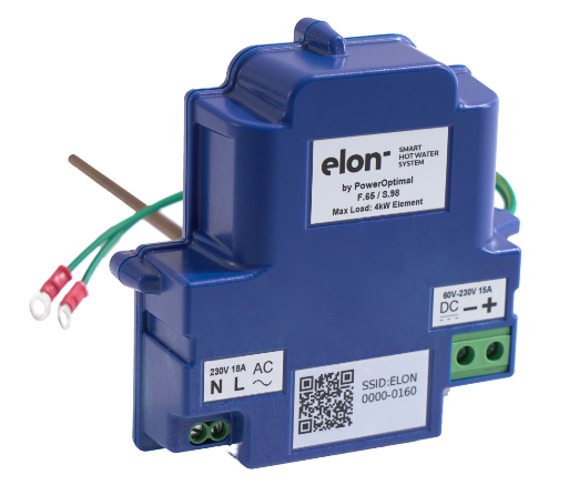
PowerOptimal Elon® Smart Thermostat
Installation Manual
Version date: 2025/12/28
Enquiries: [email protected]
Address: 88 12th Avenue
Kleinmond
7195
Please note: Always check the Elon Smart website for the latest version of this manual.
Patented: GB2583814, ZA2019/02129, ZA2022/08516, EP4100979,
US 12,112,914, GB2618349, ZA2024/08399
Patents pending: PCT/ZA2024/050065, CH2023800381161, US 18/861,142, EP4519612, AU2023264634, ZA2023/11726, ZA2024/08845

SAFETY WARNING
The Elon® Smart should only be installed in standard Kwikot electric geysers. It is NOT compatible with other geyser brands.
- We strongly recommend that the Elon Smart is only installed by a qualified plumber or electrician.
- If you are installing solar PV together with the Elon Smart, we strongly recommend that you use a reputable and experienced solar photovoltaic (PV) system installer to install your solar PV modules, and strictly according to the installation instructions in this installation manual.
- Installers should wear the appropriate safety and personal protective equipment (for example a safety harness and/or fall protection equipment when working at height).
The solar PV modules and wiring installation must be signed off by an electrical contractor registered with the Department of Labour (the so-called “wireman’s licence”) The electrician must provide you with a supplementary Certificate of Compliance (CoC) once installation is completed. (A supplementary CoC is not required if only the Elon Smart is installed with no solar PV.)
- Solar PV modules exposed to the sun are live (i.e. will produce electricity) and can give an electric shock. Special care should be taken and only trained solar PV installers should install the modules.
- Do not attempt to alter or service the electrical installation, or open the Elon® Smart unit or controller for any purpose.
- Use the Elon® Smart only for its intended purpose.
- Always make sure that every wiring connection is properly tightened.
- Do not earth either of the solar module wires (but do earth the frames).
- All installation wiring should be at least 2.5mm².
- Avoid coiling, since DC switching can create damaging spikes.
- Keep all wires as short as possible.
Refer to the PowerOptimal website for the following:
|
|
|
|
|


Table of Contents
3. Solar PV array installation 7
A. Inserting the Elon Smart unit into the geyser 9
B. Preparing and wiring the AC disconnect switch to the Elon Smart 9
C. Preparing and wiring the DC disconnect switch to the Elon Smart Thermostat 13
D. Final insertion, testing and closing the cover 13
E. Configuring the Elon Smart Thermostat using the Elon Smart App 14
F. Applying warning labels and QR code label 17
Appendix A. List of Alarms and How to Resolve Them 19
Appendix B. Basic Troubleshooting Guide for Electricians 21
C1. Solar irradiance levels 23
C3. Azimuth / horizontal angle 24
C4. Inclination or tilt angle 24
C7. Minimum distance from roof edges 25
Appendix D. Deciding on Size of Solar Array 26
Appendix E. PV array and geyser (water heater) element matching 30
Appendix F. Technical Specification Summary: Elon® Smart 31
Appendix G. Surge Protection Device (SPD) Recommendations 32
G1. SANS 10142-1 The wiring of premises Part 1: Low-voltage installations 32
Appendix H. IEC/SANS and EMC Test Certificates: Elon® Smart 36
1. Required tools
The following tools are required for the installation. Use insulated tools wherever applicable.
- Solar modules (mounting) - please refer to solar module / mounting installation instructions – the below is only a guideline:
- Cordless screwdriver with bits
- Drill
- Set of drill bits (wood, steel, stone)
- Set of screwdrivers
- Set of Allen (hex) keys
- Tape measure
- Grinder (tile roof installations)
- Permanent marker
- Chalk
- Hammer
- Solar modules (electrical):
- AC/DC Clamp meter
- Side-cutting pliers
- Screwdriver set
- Crimping tool
- 4 mm² wire (double insulated) (or other size as determined by solar PV voltage and wire length)
- Cable ties
- Elon Smart - the following additional tools:
- Insulated No. 2 Phillips or Pozidriv screwdriver
- Insulated 5mm flat screwdriver
- Wire Stripper for 1.5 -6mm wire
- Wire Cutter for 1.5 -6mm wire
- Cell phone with Elon Smart app installed
- No. 8 spanner or socket for geyser earth stud
2. Basic wiring diagram
Note 1: Both AC & DC circuit breakers or isolators must be installed within 1.5m of the geyser (water heater), line of sight.
Note 2: Surge Protection Device (SPD) only required in higher lightning strike density areas (such as parts of Gauteng and Mpumalanga), or where the DC cables are long. See Appendix F.
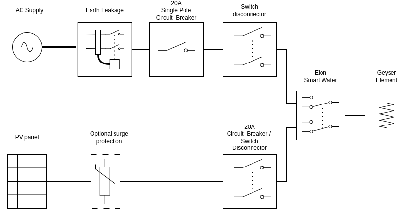
Figure 2.1 Basic wiring diagram for the Elon Smart.
3. Solar PV array installation
Modules should only be installed by a trained solar PV installation technician. Array position and orientation have a major impact on power production (see Appendix B).
Review the instructions from your solar PV module supplier / manufacturer on installation.

Please note: Your installer should comply with SANS 10142-1 (Standard for low voltage installations) and SANS 60364-7-712 when doing your solar PV installation. If they are not well familiar with these standards, you should look for a different solar PV installer.
SAPVIA (South African Photovoltaic Industry Association) has made available an excellent guide to solar PV installations. See:
NB: Refer to Appendices C & D for guidelines on selecting the right size solar PV array for the user requirements, and for correctly matching the solar PV array and the geyser element.
The below installation steps are a general guide only – compliance with the abovementioned standards is compulsory.
- A critical starting point is safety gear: ensure that all installers wear a helmet and insulated safety gloves, as well as fall protection safety gear that is securely fixed to anchor points if work will be done on a roof or elevated area.
- The solar PV array should only consist of one string of 2 to 5 modules in series, or two parallel strings 2 to 5 modules each. Do not exceed the DC voltage or current ratings of the Elon® Smart (230V DC and 15A DC) under any circumstances.
- Attach bracket / mounting structure to roof. Use mounting structure recommended by solar module supplier for roof type and size of solar modules.
- Fix the solar PV modules to the mounting structure and connect the module cables to each other.
- If practical, cover the modules to ensure that there is no potential for electric shock whilst installing the system.
- Ground the mounting structure only.
- Install the wiring from the solar PV array to the Elon® Smart unit in the ceiling space. Ensure circuit breakers / isolators are in the “Open” position. Installation of a Surge Protective Device (SPD) between the solar PV array and the Elon® Smart is required in high lightning strike areas, such as parts of Gauteng and Mpumalanga. See Appendix F for more information.
- Last step is to connect the array to the rest of the wiring, making sure that both the positive and negative wires are fully isolated from ground and keeping circuit breakers / isolators in the “Open” position.
Note: no separate earth spike is required for Elon solar PV installations. That is because the Elon never disconnects the AC supply to the house and does not interfere with the existing earthing arrangement.
Some “DO’s & DON’T’s” when installing solar PV arrays:
Your solar PV installer should not make any of these basic mistakes, but they are listed here just in case.
- DO earth the PV array structure.
- DO isolate the wires from the PV array structure.
- DO twist the DC cables together if practical.
- DON’T use different sizes, types or specifications of modules together in the same string or array.
- DON’T install solar arrays where they will be partially shaded during any season of the year if it can be avoided at all.
- DO install the arrays so that there is space for inspection or maintenance when needed.
- DO use cabling of the correct size for your solar array.
- DON’T install the solar array flush with your rooftop. Use struts / brackets that ensure an unrestricted air gap of at least 40 mm between the roof and the modules.
- DON’T walk on the modules.
- DO ensure that connectors are kept clean and away from water.
- DON’T leave exposed modules in short circuit.
- DO ensure that all connectors are securely fastened.
- DON’T exceed the voltage ratings of any components.
- DO properly route and secure all cables.
- DON’T coil cables.
4. Elon® Smart installation
A note on poor geyser installations
Poor geyser installations can cause excessive heat loss, which increases electricity cost with no benefit.
Check for the following:
- There should be lagging (insulation) installed on at least the first meter of the hot water outlet pipe and the cold water inlet pipe.
- If the hot water outlet pipe is routed upwards from the geyser, a U-bend heat trap must be installed, otherwise natural hot water convection (circulation) will cause excessive heat loss from the geyser
- The geyser itself should have good quality insulation. (All new geysers since 2013 have had to comply with more stringent insulation requirements and should have good quality insulation.)
- If there is a solar thermal system still connected to the geyser, it is strongly recommended to uninstall it, or at the very least ensure that there are closed shut-off valves on both entering and exiting pipes.
- If there is a hot water circulation system installed in the house, good insulation along the whole pipe length is critical. Circulation times should also be kept to a minimum.
- It is NOT recommended to use a geyser timer together with the Elon 100 system.
A. Inserting the Elon Smart unit into the geyser
- Make sure both the AC and the DC disconnect switches are in the off position.
- Take off geyser cover
- Take out existing thermostat
- Insert the Elon Smart Thermostat stem at least 1/3rd of the way into the pocket (see Figure 4.1). Don’t insert it fully yet.
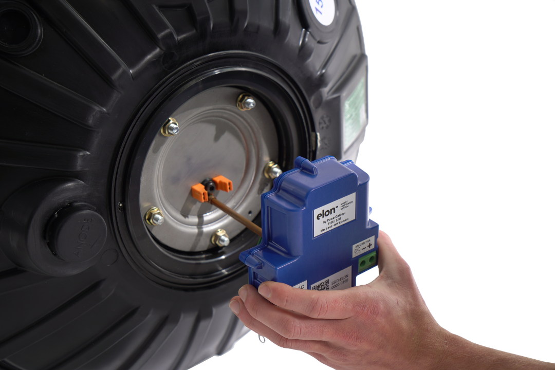
Figure 4.1. STEP 4: Insert the Elon Smart Thermostat stem at least 1/3rd of the way into the thermostat pocket. Don’t insert it fully yet.
B. Preparing and wiring the AC disconnect switch to the Elon Smart
5.
Cut a 2.5mm² flexible cord for connecting Elon Smart to the AC disconnect switch (see Figure 4.2).- The flexible cord has stranded wire which makes routing under the geyser cover much easier.
- It is not recommended to use solid 2.5mm² twin core + earth. If it is used take care, ensure wire lengths and routing do not put undue strain on the wiring causing it to be pulled out of the screw terminals when the geyser cover is put back.
- The cord needs an additional 15 cm to route under the geyser cover.
- The AC terminals on the Elon Smart can handle 1.5 – 4 mm² flexible cables, but at least 2.5 mm² is recommended.
6. Strip cord 15 cm to expose live neutral and earth wires.
7. Strip and crimp O-lug to earth.
8. Cut live and neutral wires to 8 cm and strip back the insulation by 6 mm.
9. Thread the cord through the geyser cover.
10. Connect cord to AC disconnect switch.
11. Connect the 2 Earth wires (green and yellow) coming out the right side of the Elon Smart and the earth from the AC cord to the geyser earth point (see Figure 4.3).
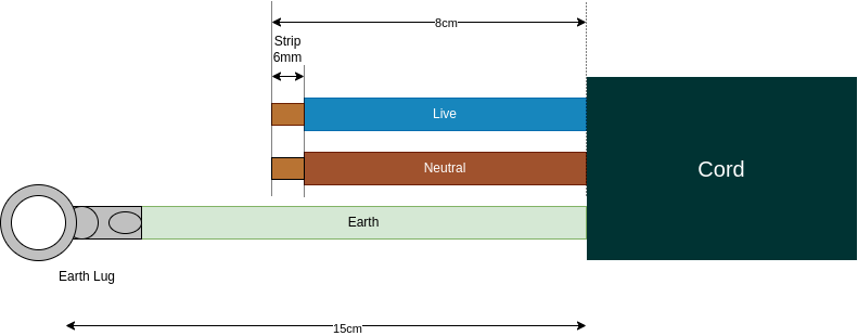
Figure 4.2. STEPS 5 – 8: Preparation of AC cord to wire between AC disconnect switch and the Elon Smart thermostat.
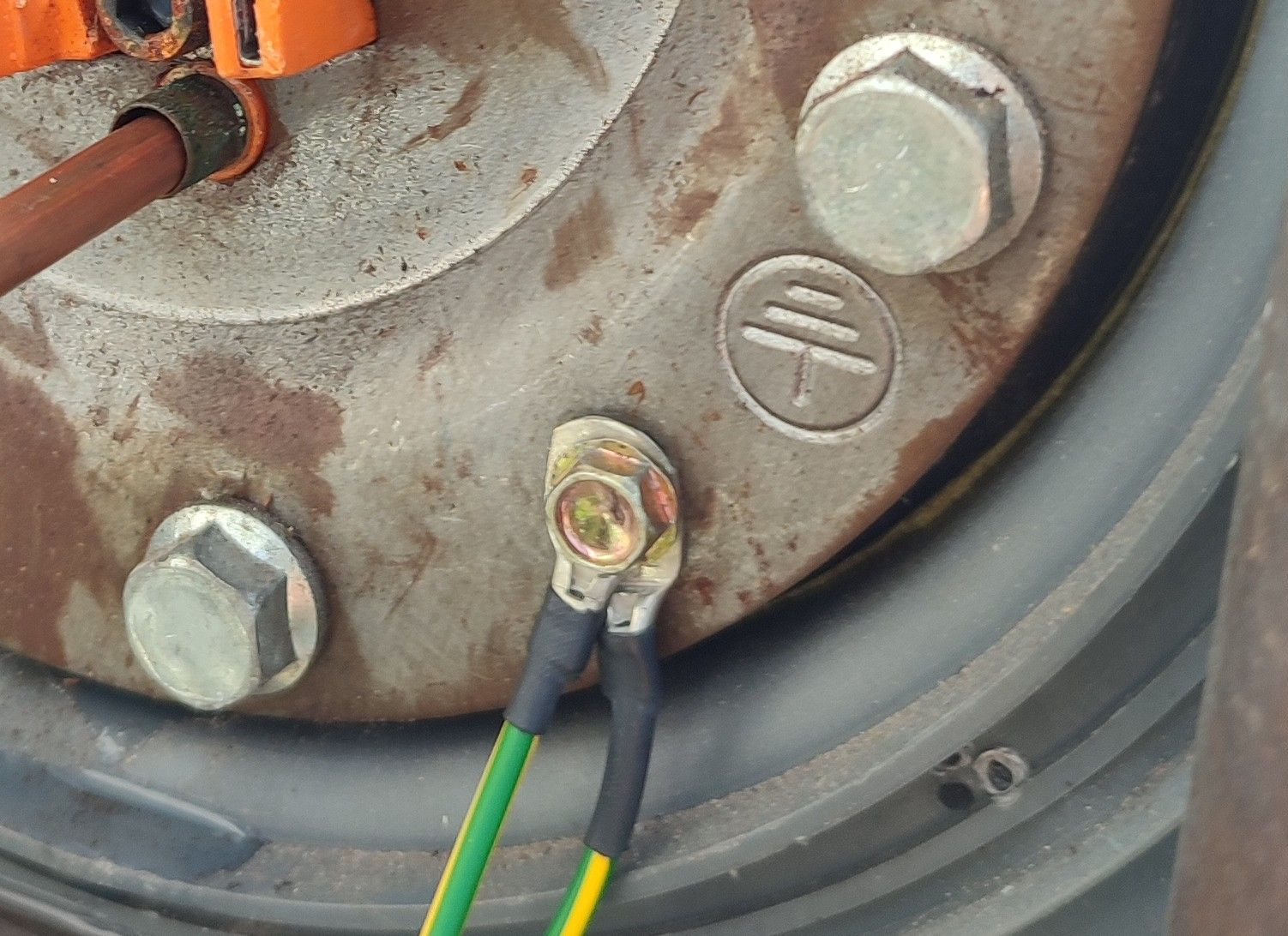
Figure 4.3. STEP 11: Connect the two earth wires (green & yellow) from the Elon Smart thermostat and the earth from the AC cord to the geyser earth point.
12.
Insert the Live and Neutral into the screw terminals labelled AC and tighten as per the following steps:a.
The AC screw Terminals are located on the left of the Elon Smart Thermostat (see Figure 4.4).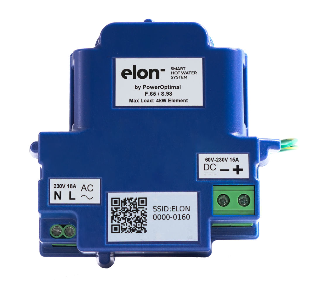
Figure 4.4. STEP 12: The AC screw terminals are located on the left of the Elon Smart Thermostat
b.
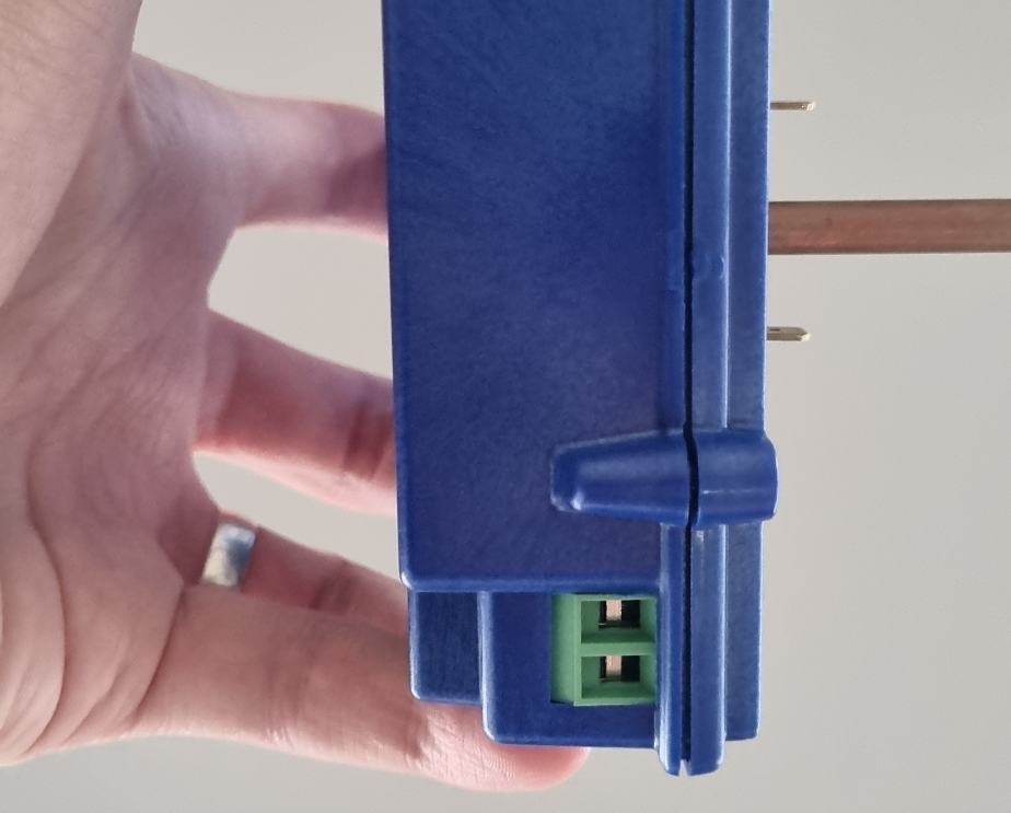
Figure 4.5. STEP 12b: Rotate the Elon Smart 90° in the thermostat pocket to make the AC wires easier to insert.
c.
d. Insert live (Brown or Red wire) into the right cage clamp marked L.
e. Insert neutral (Blue or Black wire) into the left Cage clamp marked N.
f. Make sure no strands are folded back when you insert the wires into the cage clamps before tightening.
g. For 1.5mm² solid core wire, removing the insulation for 12mm, folding back, and squeezing with a set of pliers provides a more secure fit in the cage clamp when tightening (see Figure 4.6).
h. Tug lightly on both wires to make sure they are tightened sufficiently.
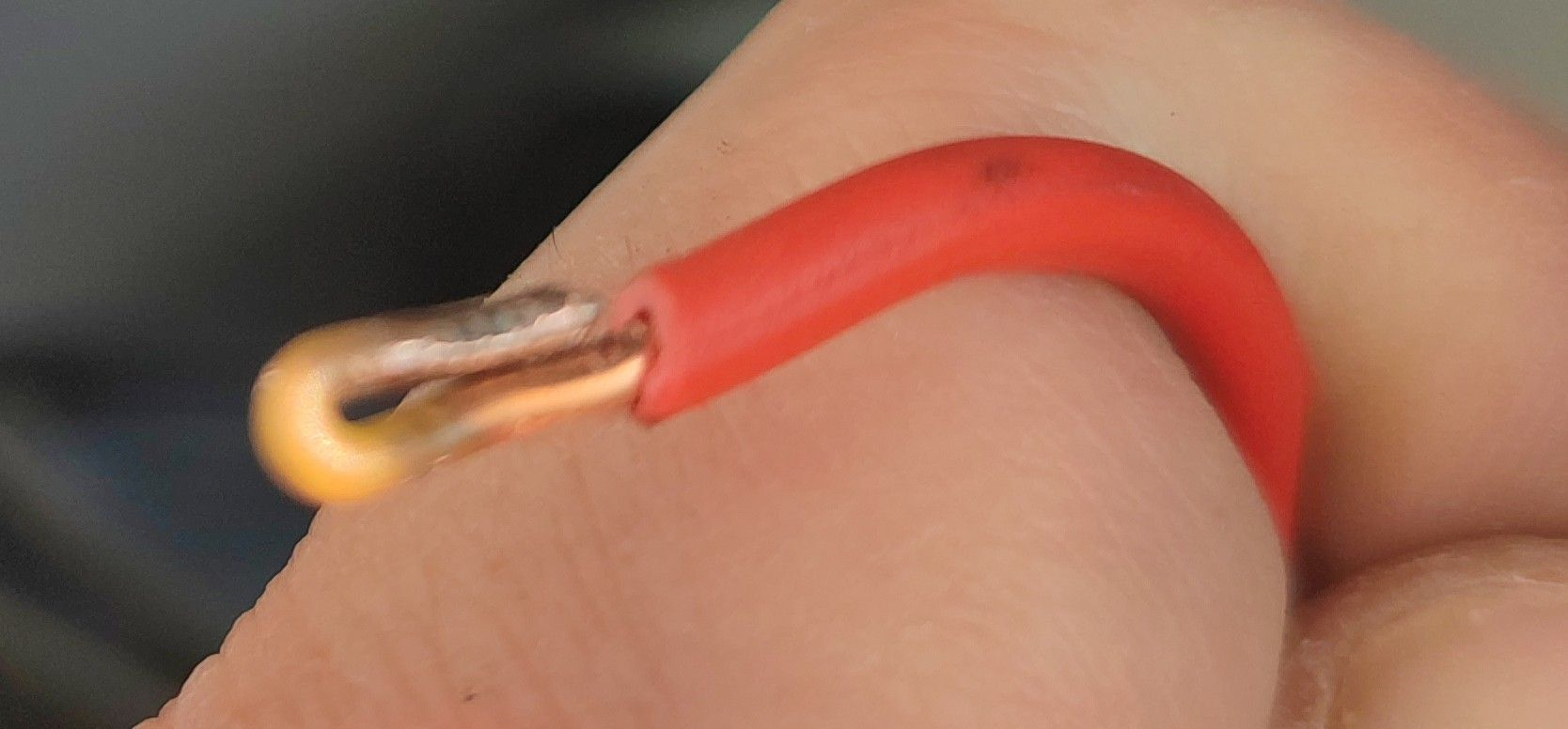
Figure 4.6. STEP 12g: for solid core wire, fold back and squeeze the wire with a set of pliers to give the cage clamp a better grip.
C. Preparing and wiring the DC disconnect switch to the Elon Smart Thermostat
- Cut 2 pieces of solar double insulated wire for connecting Elon Smart to DC disconnect switch.
- The DC terminals of the Elon Smart can handle 2.5 – 6 mm² flexible cable, but 4mm² or 6mm² double insulated UV protected solar wire is recommended to minimise wiring losses.
- 4mm² or 6mm² stranded wire clamps better than 2.5mm² wire in the screw terminals.
- Bootlace ferrules can be used but are not required.
- Connect one end of the wires to the DC disconnect switch.
- Strip the other end of both wires to 10 mm.
- Thread wires through geyser cover.
- Insert the Solar Wires into the screw terminals labelled DC and tighten using a No. 2 Phillips screwdriver.
- The DC screw Terminals are located on the right of the device.
- Open the cage clamps fully by screwing counterclockwise before inserting the wires to make sure the wire is inserted into the cage clamp and not the space below.
- The wires are easier to insert if you rotate the Elon Smart 90° or 180° in the geyser socket. This gives a clear view of the screw terminals cage clamp.
- Insert DC + (positive) into the right cage clamp marked +
- Insert DC - (negative) into the left cage clamp marked -
- Make sure no strands are folded back when you insert the wires into the cage clamps before tightening.
- If the wires are stripped to the required 10mm, the wires can be inserted into the cage clamp up to the insulation before tightening.
- If using an electric screwdriver with a torque setting, tighten to 1.2 Nm.
- Give the wires a light tug to make sure they are tightened securely.
D. Final insertion, testing and closing the cover
- Press the Elon Smart thermostat into the Element making sure the blade terminals at the bottom fully engage with the element. It should press in quite firmly.
- On new geysers with a standard double recess Kwikot end plate the Elon Smart thermostat should fit flush to the plate.
- Turn on the DC disconnect switch.
- Verify DC is present on the DC screw terminals (see Figure A1 in Appendix A).
- Take care as the screws of the screw terminals are live;
- Verify DC polarity is correct.
- Turn on the AC disconnect switch.
- Verify AC is present on the AC screw terminals (see Figure A2 in Appendix A).
- Turn off the AC and DC disconnect switches.
- Scan the QR code of the Elon Smart thermostat with the Elon Smart app before closing the cover.
E. Configuring the Elon Smart Thermostat using the Elon Smart App
- Install the Elon Smart app on your smart phone by searching for “Elon Smart Water” in the Google Play Store (Android) or Apple App Store (iPhone). Alternatively, scan one of the QR codes provided below using your phone camera.
NOTE: if you have already installed the app on a previous occasion, please check that you have the latest version of the app by visiting the app page in your phone’s app store and tapping on “Update” if you don’t have the latest version. For convenience, you can scan one of the below QR codes to go to the app page in your app store.
Elon Smart App
for iPhone:
Apple App Store
Elon Smart App for Android:
For Android: Google Play Store
Scan this QR code with your Android phone Scan this QR code with your iPhone to
to install the app from the Google Play Store install the app from the Apple App Store
- Once installed the application should display the startup screen (Figure 4.7)
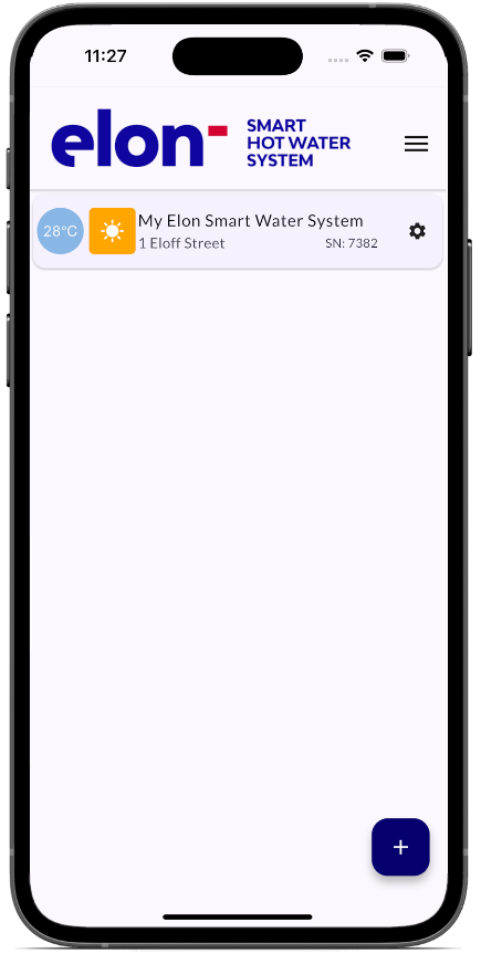
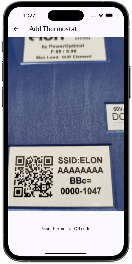
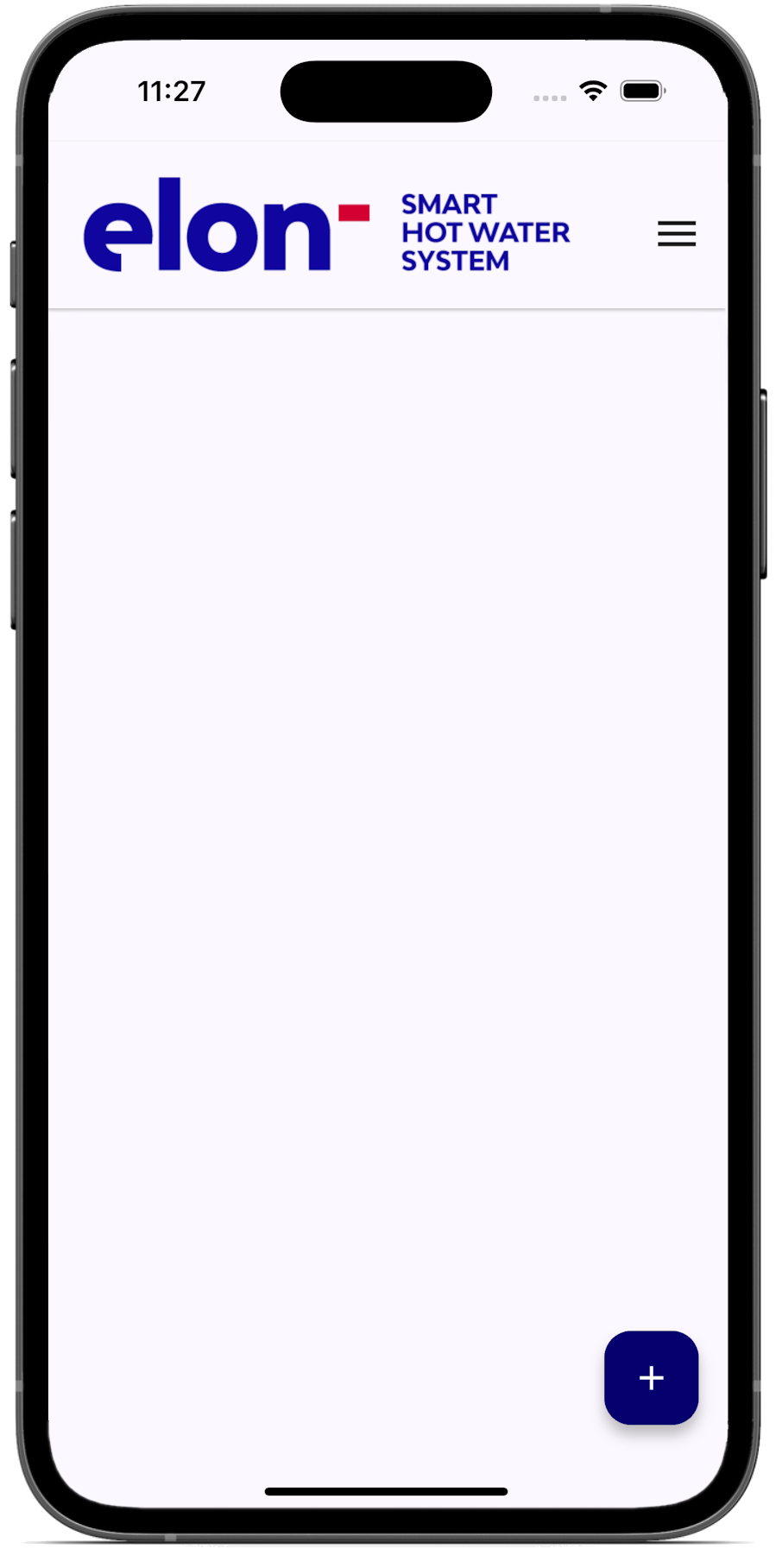
Figure 4.7 Left to Right: Start-up screen Figure 4.8screen, Scanning screen Figure 4.9screen, Thermostat added

- Tap the (+) button on the bottom right to add the Smart thermostat.
- The app will display the scanning screen called “Add Thermostat” (Figure 4.
87). Scan the QR code by placing it horizontal and centred on the screen. (If the code does not want to scan, try moving the phone closer and further from the QR code. Try rotating the phone into landscape mode.) 
97).- Tap the ⚙️ Settings (gear) button on the right of the newly added thermostat.
- The application requests confirmation to switch to the Smart Thermostat’s hotspot (Figure 4.
108). - Select “CONNECT”
- The application should display the “Thermostat Settings” screen (Figure 4.
118)  First configure the Wi-Fi network that the unit will use to connect to the server. Tap the “Wi-Fi Hotspot” item .
- The application searches for the available networks and displays them in a list (Figure 4.
128).
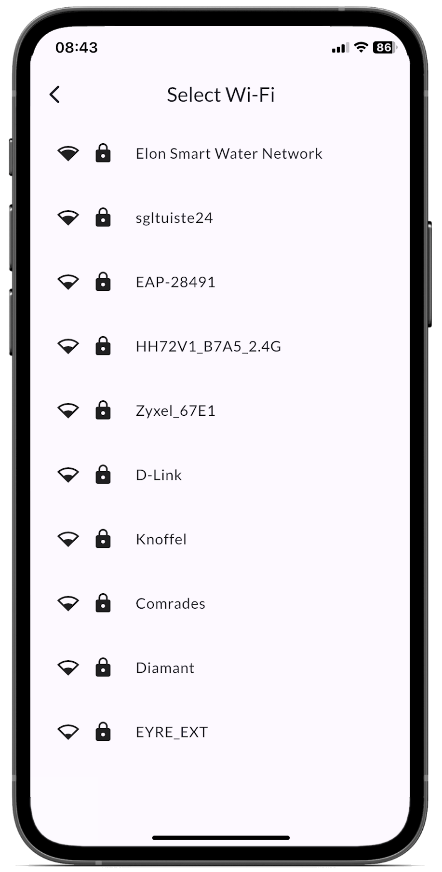
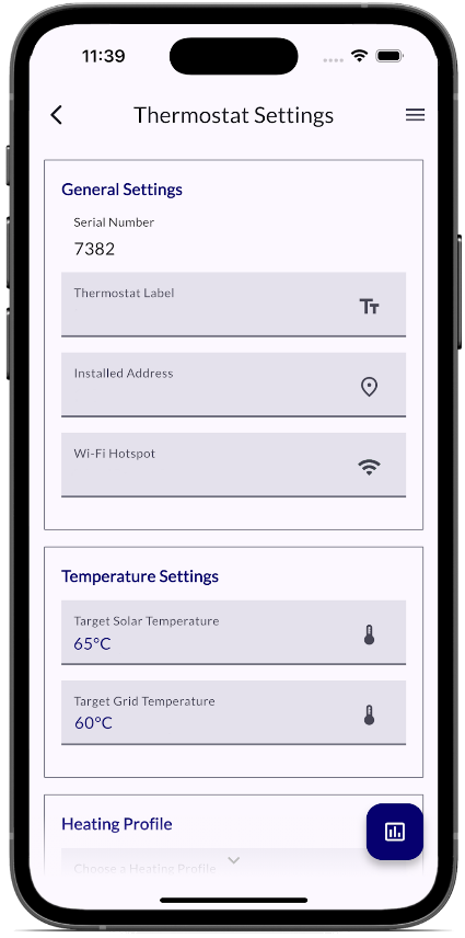
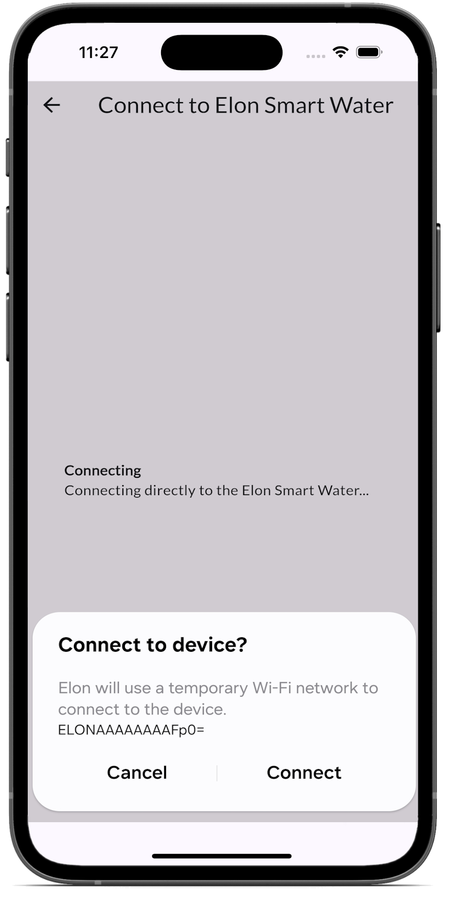
Figure 4.108 Left to right: Network change Figure 4.11change; Settings screen Figure 4.12screen; Select Wi-Fi
- Tap on the Wi-Fi network you want the Smart Thermostat to use.
- The application will ask for a password for the network you selected (Figure 4.
139). - Enter the password and tap “Test Connection”.
- If you entered the password correctly the application should take you back to the configuration screen and the network should be green.
 Next configure the address. Tap the “Installed Adress” item.
- The app should connect to the server and obtain a list of addresses corresponding to your GPS co-ordinates (Figure 4.
149). (You might need to switch on your phone GPS and allow the app to use your location services.) - Select the correct address.
- The app should take you back to the “Thermostat Settings” screen (Figure 4.
159).  Go to the top field called “Thermostat Label” and enter a new name for the smart thermostat. This will be used to identify this smart thermostat or geyser in your app.
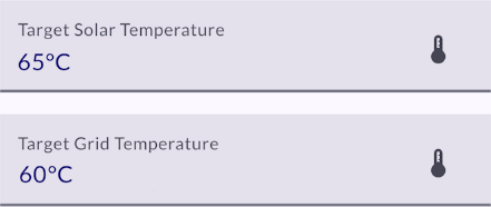 Now set the “Target Solar Temperature” and “Target Grid Temperature” set points. It is best for savings and optimal solar power usage to select a lower temperature set point for grid power than for solar power. 65 °C on Solar and 50 °C on Grid are good set points.
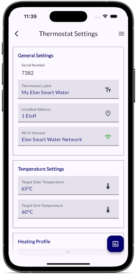
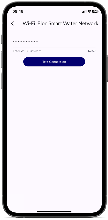
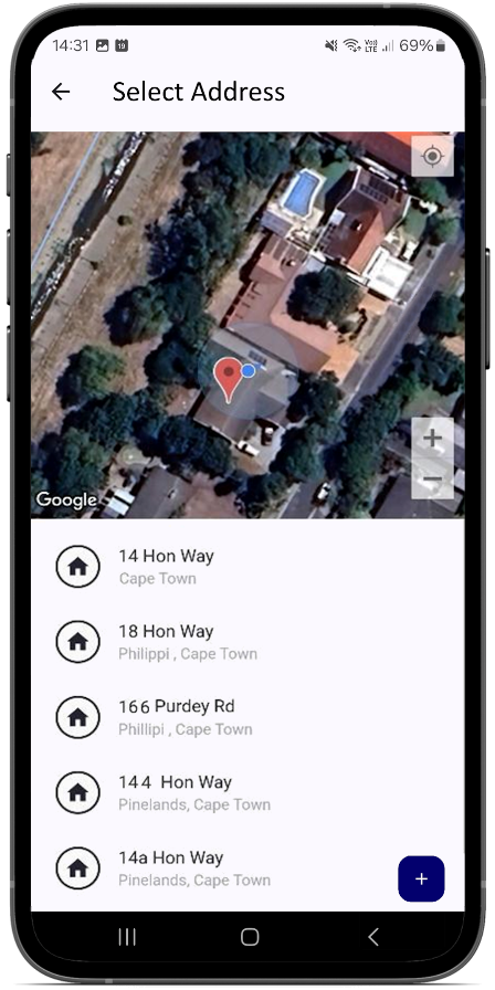
Figure 4.139 Left to right: Enter Wi-Fi password Figure 4.14password; Select address Figure 4.15address; Heating settings
- Next you can set the “Heating Profile” according to your preference (see
FiguresFigure 4.16 and 4.1710). Select how the household wishes to use the hot water generated by the Smart thermostat (Table 4.1). It is typically best to start with the “Morning and Evening Shower” profile.
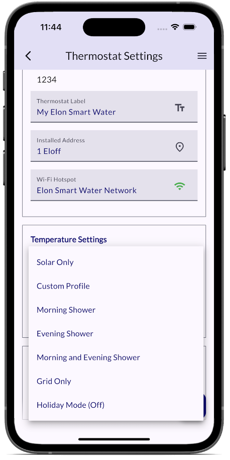
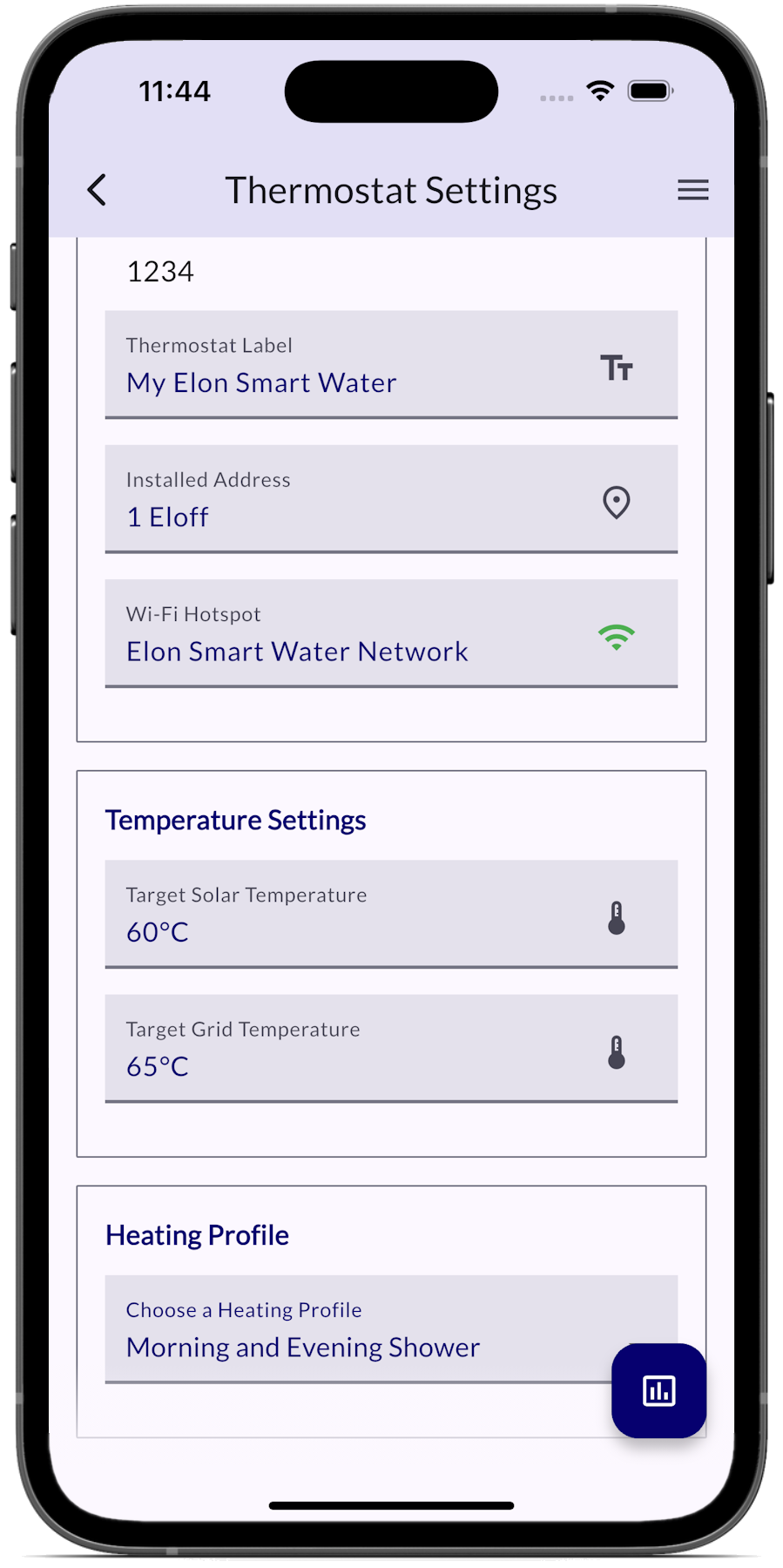
Figure 4.1610 Left to right: Heating Profile settings Figure 4.17settings; Select Heating Profile
Table 4.1 Heating Profile options
|
Heating Profile option |
Solar power use |
Grid power use |
Comments |
|
Grid Only |
Never |
Always |
Select this option if you don’t have any solar panels installed. |
|
Solar Only |
Always |
Never |
ONLY use solar power. NEVER use grid power. |
|
Morning Shower |
Always except for 3 am – 5 am |
3 am – 5 am |
Solar power will be used whenever available, and grid power will only be used early in the morning to boost water temperature to the Grid set point if the temperature is lower than that. |
|
Evening Shower |
Always except for 5 pm – 7 pm |
5 pm – 7 pm |
Solar power will be used whenever available, and grid power will only be used in the late afternoon to boost water temperature to the Grid set point if the temperature is lower than that. |
|
Morning and Evening Shower |
Always except for 3 am – 5 am & 5 pm – 7 pm |
3 am – 5 am & 5 pm – 7 pm |
Solar power will be used whenever available, and grid power will only be used in the early morning and late afternoon to boost water temperature to the Grid set point if the temperature is lower than that. |
|
Holiday Mode |
Off |
Off |
System switched off completely |
|
Custom Profile |
Whenever not in grid mode |
Custom |
Use the Custom Profile option to set your own grid heating timers. |
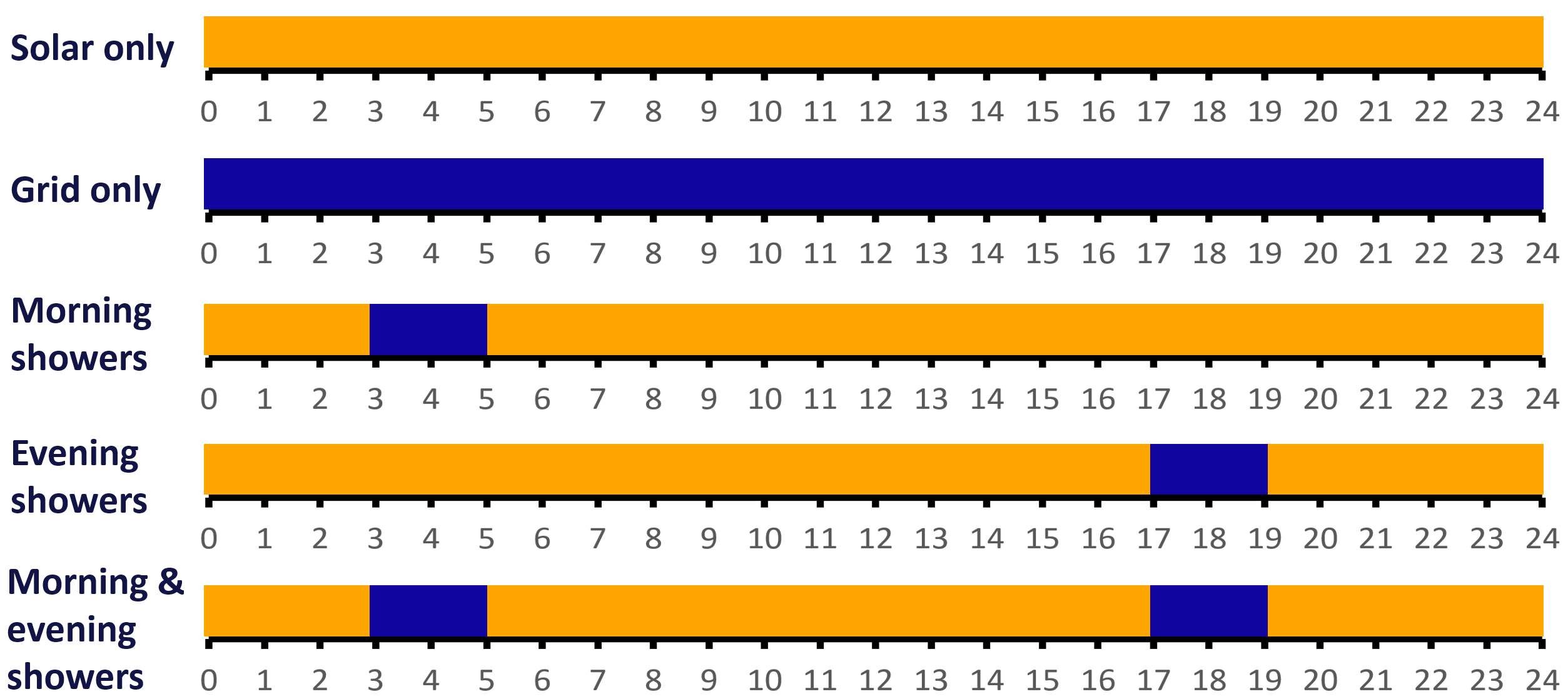
Figure 4.18 Standard Heating Profiles (solar in orange, grid in blue)
- Custom grid heating profile settings
- If you want to set your own times for when the water should be heated with grid power, select the “Custom Profile” heating profile (see Figure 4.
19)11). 
20)11). If you have not configured any custom grid heating profiles yet or want to add a custom profile, tap “New Profile”.
- You can also edit an existing profile by selecting that profile and tapping “Edit Profile”.
- Once you’re on the custom profile editing screen (see Figure 4.
21)11), give your custom profile a name so you can easily select it in future.  You can add time slots for grid heating for the different days of the week, as well as target water temperatures. Note that you can add multiple time slots in a single custom profile by tapping “Add Additional Timer”.
 Once done with setting up your custom grid heating profile, don’t forget to tap “Save”.
- If you want to set your own times for when the water should be heated with grid power, select the “Custom Profile” heating profile (see Figure 4.
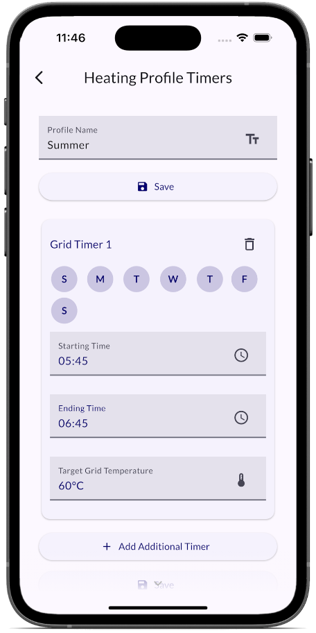
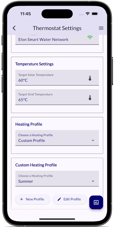
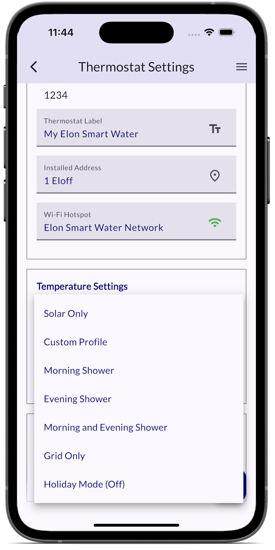
Fig 4.1911 Left to right: Select “Custom Profile” Fig 4.20; Choose a custom profile Fig 4.21profile; Set grid time slots
- If there are any problems with the installation, an alarm will display below the thermostat settings, indicated by a red exclamation mark (!). See Appendix A for a list of alarms and how to resolve them (if needed).
- Once you have cleared all the issues, then no more alarms will be displayed on the configuration settings screen.
Please note: DO NOT install a separate timer on the AC side to try and regulate mains power use. Use only the Elon Smart app to control mains power use. If you install a second timer, it will work at cross-purposes with the Elon and you will reduce performance and hot water availability.
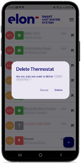
To delete a smart geyser from the app, tap and hold on the device that you want to delete on the home screen.
A prompt will pop up for you to confirm whether you want to delete the device, as shown on the screenshot to the right.
G. How to view app and device software versions
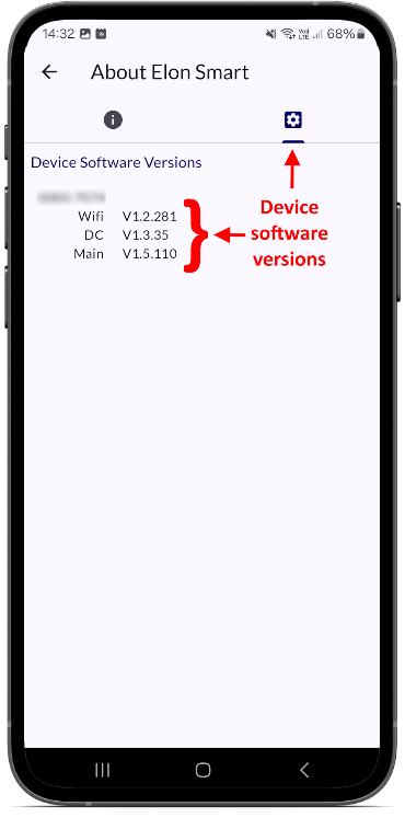
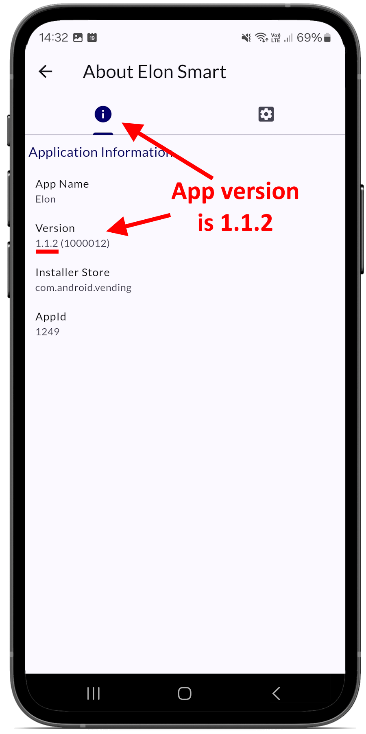
To see the current version of the app and the current versions of all software on the Elon Smart Thermostat, tap on the hamburger menu ≡ in the top right of the home screen and then tap “About”. The left tab shows the mobile phone app version, whilst the right tab shows the device software versions.
H. Applying warning labels and QR code label
- Attach labels included with the Elon Smart (see Figure 4.16 below):
- Attach "Dual Supply" labels (a) to the AC isolator and the DC circuit breaker (or isolator).
- Attach "Warning – Photovoltaic Power Source" label (b) to the DC wiring conduit in a clearly visible position.
- Attach “Warning – disconnect supply circuits” label (c) to outside of geyser end cover.
- Attach Elon Smart QR code label (d) to the inside of the house’s DB board.
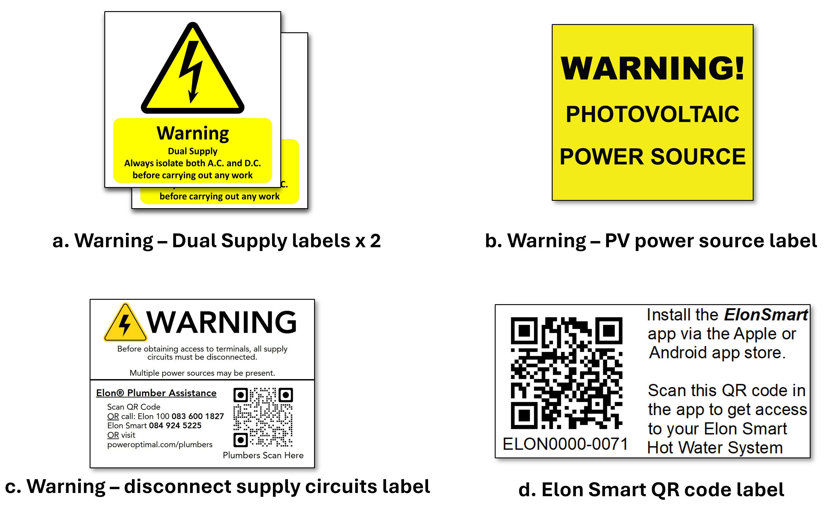
Figure 4.16. Labels included with the Elon Smart
Final step: hand over the Quick Start User Guide (included in the box) to the household (or leave it in a prominent place for them to find such as the kitchen counter).
Appendix A. Basic Troubleshooting for Users, List of Alarms and How to Resolve Them
Here is a flow diagram with basic troubleshooting steps for users. Always check that you have the latest version of the app by going to the “Elon Smart Water” app in your app store.
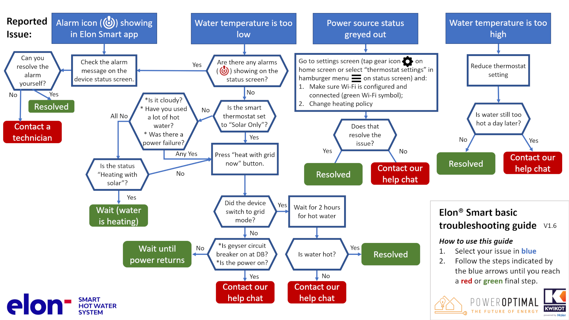
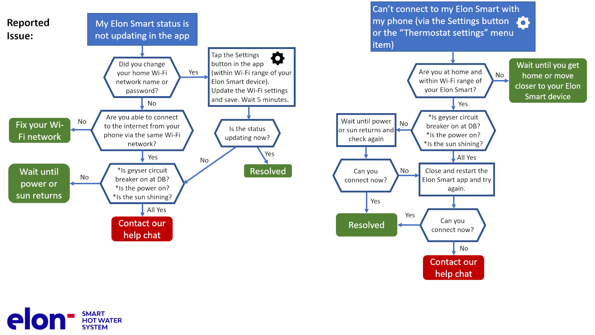
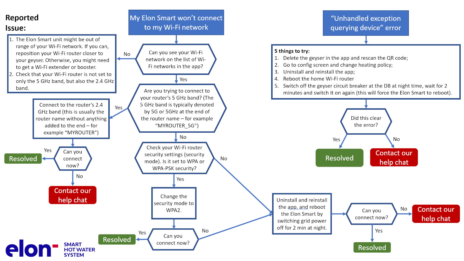
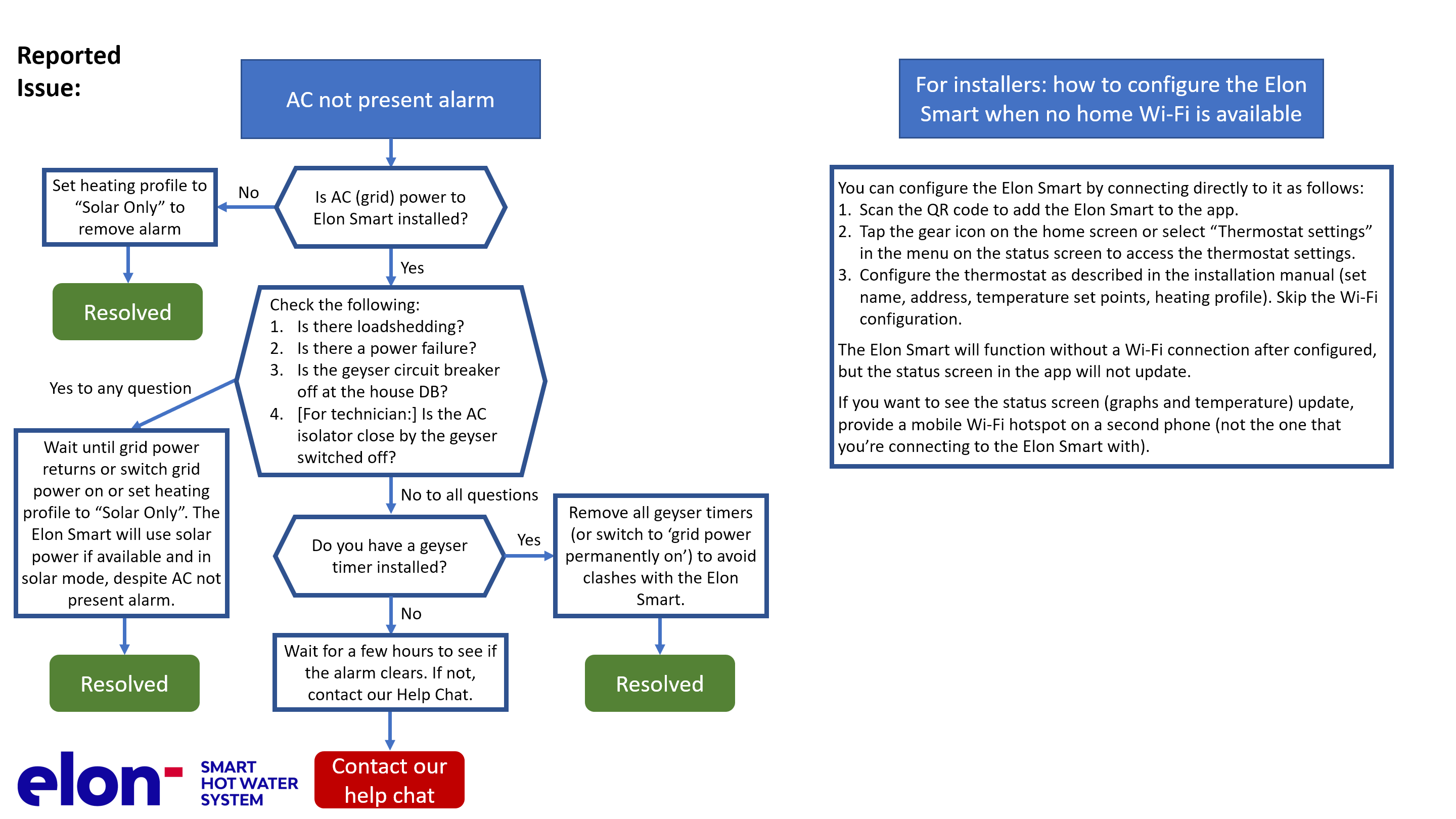
The Elon Smart has a helpful alarm system that detects and reports common issues. See the below list for the various alarms and how to resolve them.
|
ID |
Alarm message |
How to resolve the alarm |
|---|---|---|
|
0 |
Element Faulty |
a. Check that the thermostat is inserted correctly. b. If that does not clear the alarm, measure element resistance and replace if necessary. |
|
1 |
Switch Failed |
Contact our help chat |
|
2 |
DC Disconnect Failed |
Contact our help chat |
|
3 |
No Power on AC Input |
This can be due to several reasons: a. There is no AC power connected to the Elon Smart b. AC power is off at the circuit breaker in the DB board or at the AC isolator close by the Elon Smart unit. c. There is a power failure or loadshedding. d. You have a geyser timer installed. This alarm won’t prevent the Elon Smart unit from functioning and heating water with solar (DC) power as long as there is solar power available. You can clear the alarm by switching the AC power on (where applicable), setting the Elon Smart heating policy to Solar Only (see Table 4.1) or you can leave it until AC power returns. |
|
4 |
Measurement Failure |
Contact our help chat |
|
5 |
Disconnected for Safety |
When there is a safety-related alarm condition, the Elon Smart will disconnect power from the geyser. To clear this alarm, you need to clear the other safety-related alarm(s). |
|
6 |
Water Temperature Measurement Failure |
Contact our help chat |
|
7 |
Ambient Temperature Exceeded |
a. Check the installation. If the geyser is installed in direct sunlight, see if you can provide shade to the geyser end space area where the Elon Smart is located. b. Reduce temperature set point by 5 degrees. c. Wait until temperatures cool down. The Elon Smart will start up again. d. Contact our help chat if the above doesn’t clear the alarm. |
|
8 |
DC Wiring Insulation Failure |
a. Check solar panels and DC wiring for insulation faults. b. To operate the Elon Smart whilst the insulation fault has not been located and resolved, you can set the heating profile to Grid Only or switch off the DC disconnect switch. |
|
9 |
Insulation Self-Test Failed |
a. Check earth wiring. Make sure both earth straps are connected securely to the geyser earth stud. |
|
10 |
AC Wired to DC Input |
Wire AC to correct input (see Chapter 4). |
|
11 |
DC Wired to AC Input |
Wire DC to correct input (see Chapter 4). |
|
12 |
No Power on DC Input |
This can be due to several reasons: a. There is no DC power connected to the Elon Smart b. DC power is off at the DC disconnect switch close by the Elon Smart unit. c. There is an issue with the DC wiring or solar PV installation. d. It is extremely dark and overcast during daytime. (The alarm is not active when the sun is less than 15 degrees above the horizon.) This alarm won’t prevent the Elon Smart unit from functioning and heating water with grid (AC) power as long as there is grid power available. You can clear the alarm by:
|
|
13 |
DC Input Reversed |
The wiring on the Solar input has been installed incorrectly (in reverse). The DC+ (positive) wire has been connected to the DC- (negative) terminal on the Elon Smart and the DC- (negative) wire has been connected to the DC+ (positive) terminal on the Elon Smart. Swap the DC wires around (see Chapter 4). |
|
14 |
Hot Connection |
Elon Smart not correctly inserted into geyser element. Switch off all power to the Elon Smart and re-seat (reinsert) the Elon Smart. |
|
15 |
RTC Failed |
Contact our help chat |
|
16 |
Power Unstable |
|
|
17 |
Server Not Available |
If none of the above works, try rebooting your Elon Smart by switching off the geyser circuit breaker on your house DB board at night for 2 minutes. |

Appendix B. Basic Troubleshooting Guide for Electricians
NOTE: This Troubleshooting Guide is intended for electricians and not general users.
Things to Remember
- After power up, the unit runs a self-test that takes about 30 seconds. Once the self-test passes the unit will engage the correct power source determined by the heating policy. If the water is below the temperature set point for the source (Grid or Solar), it will start heating water. You should hear a click when this happens.
- Make sure that the wires are connected to the Elon Smart terminals securely (do a tug test with AC & DC power to the Elon Smart switched off) and check that the terminals have not been damaged (for example by overtightening).
- If the two earth wires are not connected to the earth stud the unit will fail the self-test and never start the heating process.
- Check for any geyser timers and bypass them completely or set them to “always on”.
- If you are having DC power supply issues, check if the DC circuit breaker or isolator is faulty by measuring the voltage across the DC circuit breaker or isolator whilst DC power is being supplied to the element. If there is a voltage drop across the disconnect switch, it is faulty and needs to be replaced. Also check all DC fuses if installed.
- The unit will detect the following installation faults and display them on the configuration screen. These will stop the unit from connecting power to the element until they are cleared:
- DC + and DC – are reversed (reversed polarity);
- The earth straps are not connected to the earth stud;
- AC is connected to DC input;
- There is a fault between the solar wiring and earth (insulation failure);
- Element faulty (this may happen if you insert the unit so only a single spade connector makes contact with the element);
- Unit component failure.
- The unit will also warn the installer if there is:
- No power on the AC input. The alarm is not shown if heating policy Solar Only is selected.
- No power on the DC input and it is daytime. The alarm is not shown if heating policy Grid Only is selected.
- For any Heating policy except Grid Only, solar power is normally engaged except for the periods listed in Table 4.1.
- If the unit has no grid power and engaging the element causes the DC voltage of the solar panels to drop below the voltage required to power the unit, the unit disconnects the element. If AC power is supplied, then the unit can run down to 0 V on DC. If the unit disconnects the element, it will stay disconnected for 2 minutes before connecting to the element again.
- If the unit is connected to the grid, it may draw a small amount of power (<3W) from the grid even if Solar Only heating policy is selected.
- How to switch on solar power to element: Select Solar Only heating policy on the Thermostat Settings screen.
- How to switch on mains power to element: Select Grid Only heating policy on the Thermostat Settings screen.
Troubleshooting Steps
- Open the Elon Smart app and go to the Thermostat Settings screen. Look at the alarms on the bottom of the screen and follow the instructions.
- If you cannot access the unit through the application confirm that:
- The DC isolator is closed;
- The AC isolator is closed.
- If you still cannot access the unit through the app, remove the geyser pocket cover and:
- Visually inspect the wiring ensuring that AC and DC wiring are still inserted into screw terminals;
- Check using a voltage meter that DC voltage is present on the DC screw terminals and polarity is not reversed (Figure A1);
- Check using a voltage meter that AC voltage is present on the AC screw terminals (Figure A2).
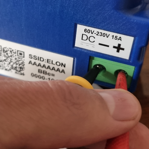
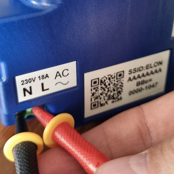
Figure A1A Left to right: Checking DC voltage Figure A2voltage; Checking AC voltage
Appendix C. Solar yield
Note: only basic information is provided here. Your solar PV installation design engineer or technician should advise on the best configuration for your specific location, roof structure, etc.
The yield produced by solar PV modules depends on several factors:
- Solar irradiance levels at your location (which varies with time of day, season and weather conditions)
- Geographic features at your location (e.g. mountains or buildings causing morning or afternoon shade)
- Azimuth and tilt of the modules
- Shading
- Ambient temperature (also influenced by wind)
C1. Solar irradiance levels
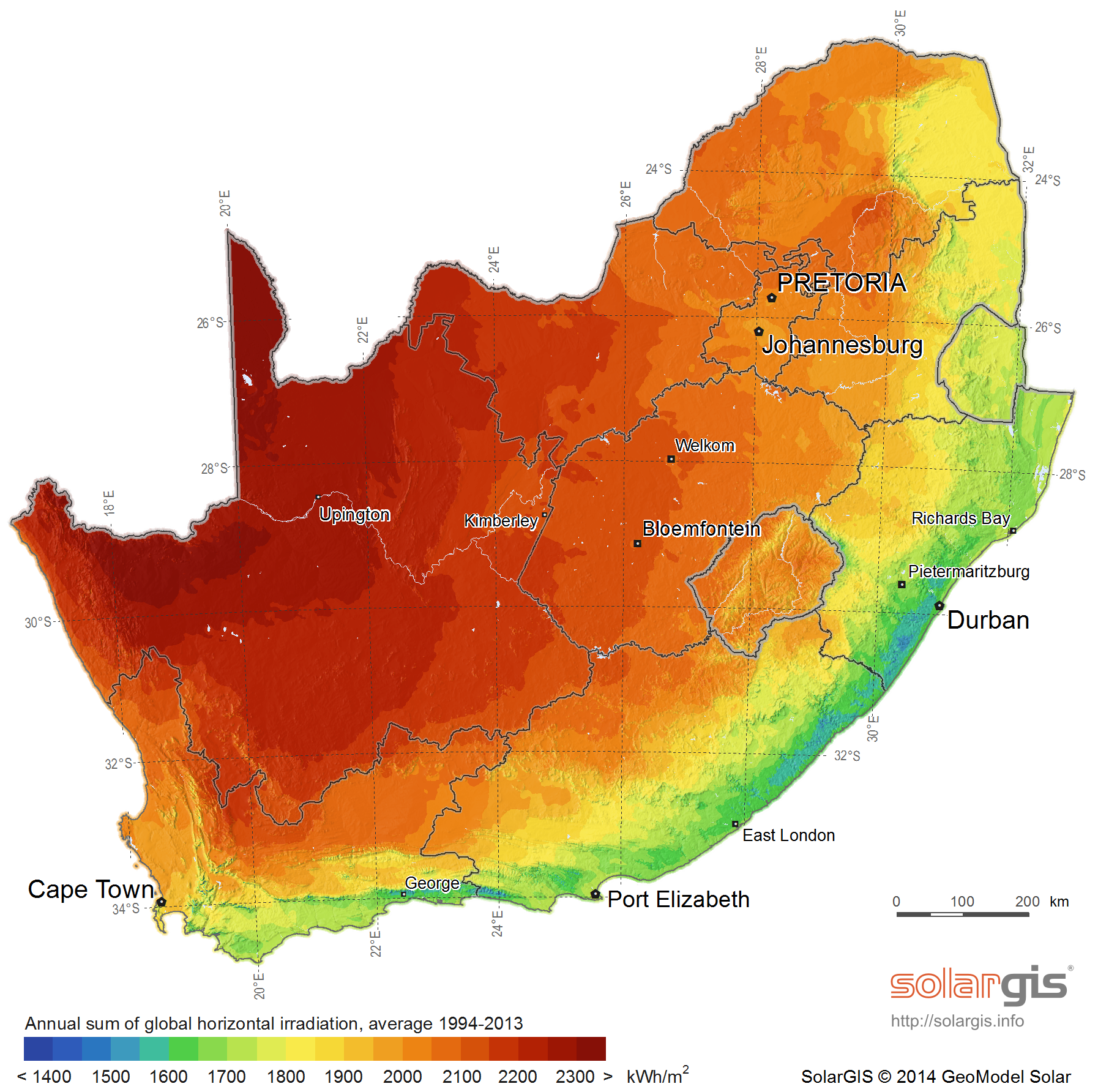
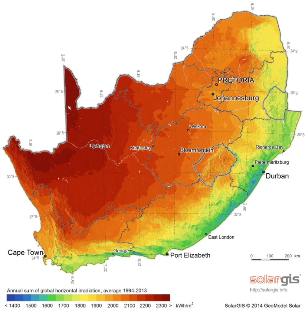
The map below shows the general solar irradiance levels (GHI or Global Horizontal Irradiance) in South Africa[1]:
You can expect the following approximate energy generation from solar modules for various locations[2]:
|
Location |
Electricity generated kWh/kWp per year |
|
Bloemfontein |
2055 |
|
Cape Town |
1762 |
|
Durban |
1570 |
|
Johannesburg / Pretoria |
1871 |
|
Mbombela |
1766 |
|
Port Elizabeth |
1698 |
|
Upington |
2075 |
C2. Geographic features
Major geographical features (such as hills or mountains) can reduce the total solar yield.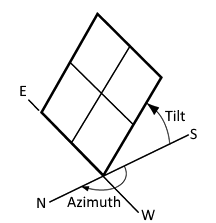
C3. Azimuth / horizontal angle
The azimuth refers to the horizontal orientation of the modules – in the Southern Hemisphere, by how many degrees they are oriented away from north
Due north is best in the Southern hemisphere. Modules should preferably not be oriented more than 15º away from due north.
C4. Inclination or tilt angle
The tilt angle refers to the vertical orientation of the modules – a rough guide is that the modules should be tilted at the site’s latitude. For example, Musina is 22º S, Pretoria & Johannesburg are 26º S, Bloemfontein is 29º S, Durban is 30º S and Cape Town & Gqeberha (Port Elizabeth) are 34º S.
To optimise winter performance, one can add 15º to the tilt angle. (Note: as long as you are within about 15º of the optimal latitude, the loss in efficiency is not substantial.)
C5. Shading
Solar modules lose a lot of efficiency if even a small part of the module is shaded. For example, just 3% shading can cause a 25% loss in power! Shaded cells on a module also causes hotspots, which will reduce module lifetime.
It is thus important to place the solar modules on a rooftop area that is free from shading for as much as possible of the day (and throughout the year).
C6. Ambient temperature
Solar PV modules’ performance decreases with increasing temperature. Wind will reduce the temperature of the solar array and will thus improve performance. Thus, it is important to install rooftop solar modules with an air gap of at least 40 mm between the modules and roof[3].
C7. Minimum distance from roof edges
Your solar PV design engineer should prescribe minimum clearance from roof edges that should be maintained for your area based on climatic and wind conditions. Typically, a minimum clearance of 20 to 30 cm should be maintained.
Appendix D. Deciding on Size of Solar Array
Terminology used
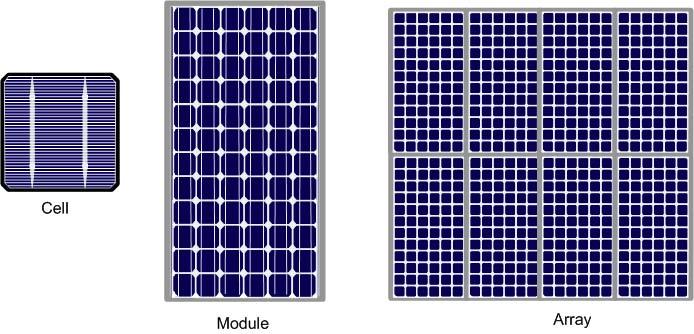
Solar power is generated by solar cells, which are arranged in framed modules. The total set of solar PV modules installed is referred to as a solar PV array[4].
The table below provides a basic guide to selecting the size of the solar PV array based on number of people in the household and/or hot water use. Minimum recommended size is 1 kWp. Read on for a more detailed guide.
|
Solar PV array size (kWp) |
Showers per day* |
50%+ of daily hot water use provided for how many people? |
How many people off-grid for hot water? |
Typical number of solar PV modules |
|
1 – 1.6 |
   |
   |
  |
2 - 3 modules |
|
1.6 - 2 |
       |
    |
   |
3 - 4 modules |
|
2 - 3 |
   |
     |
    |
4 - 5 modules |
* 6-minute showers at 40 °C with 8 litre/min (low-flow) showerheads
TABLE D1. ANNUAL AVERAGE LITRES OF WATER HEATED PER DAY
The below example table indicates the average number of litres of water per day that the system will heat from 15 to 60 °C over a year period for different solar array peak power ratings. (The amount of water heated will vary with weather conditions, by geographic location and by season. Water heated per day will be significantly lower in winter and significantly higher in summer. These numbers indicate heating capacity – i.e. if no hot water is used on a given day, there will be less water heated on that day. This is only an approximate guide.)
|
|
Solar + Elon® |
Annual average litres of water heated per day for X kWp installed solar capacity |
||||||||||||||||
|---|---|---|---|---|---|---|---|---|---|---|---|---|---|---|---|---|---|---|
|
Location |
kWh/kWp/yr |
0.8 kWp |
1 kWp |
1.2 kWp |
1.4 kWp |
1.6 kWp |
1.8 kWp |
2 kWp |
2.5 kWp |
3 kWp |
3.5 kWp |
|||||||
|
Bloemfontein |
1894 |
80 |
99 |
119 |
139 |
159 |
179 |
199 |
249 |
298 |
348 |
|||||||
|
Cape Town |
1624 |
68 |
85 |
102 |
119 |
136 |
154 |
171 |
213 |
256 |
299 |
|||||||
|
Durban |
1447 |
61 |
76 |
91 |
106 |
122 |
137 |
152 |
190 |
228 |
266 |
|||||||
|
Jhb/Pretoria |
1724 |
72 |
91 |
109 |
127 |
145 |
163 |
181 |
226 |
272 |
317 |
|||||||
|
Mbombela |
1627 |
68 |
85 |
103 |
120 |
137 |
154 |
171 |
214 |
256 |
299 |
|||||||
|
Gqeberha (PE) |
1565 |
66 |
82 |
99 |
115 |
132 |
148 |
164 |
205 |
247 |
288 |
|||||||
|
Upington |
1912 |
80 |
100 |
121 |
141 |
161 |
181 |
201 |
251 |
301 |
352 |
|||||||
|
Saldanha |
1623 |
68 |
85 |
102 |
119 |
136 |
153 |
170 |
213 |
256 |
298 |
|||||||
Example:
For a solar array of 1.2 kWp, an installation in Johannesburg would yield about 1724 kWh/kWp/yr, or 1724 x 1.2 kWp = 2069 kWh/yr. This would be sufficient to heat on average 109 litres of water per day. For a family of 2 each using 80 litres of hot water per day, this would provide about 109 ÷ (80 x 2) or 68% of the annual hot water requirement.
TABLE D2. ANNUAL AVERAGE NUMBER OF SHOWERS PER DAY
The below table indicates the average number of showers per day for which the system will supply hot water over a year period for different solar array peak power ratings. (The amount of water heated will vary with weather conditions, by geographic location and by season. Water heated per day will be significantly lower in winter and significantly higher in summer. These numbers indicate heating capacity – i.e. if no hot water is used on a given day, there will be less water heated on that day. This is only an approximate guide.)
|
|
Solar + Elon® |
Number of showers per day (based on annual average) for X kWp installed solar capacity |
|||||||||
|
Location |
kWh/kWp/yr |
0.8 kWp |
1 kWp |
1.2 kWp |
1.4 kWp |
1.6 kWp |
1.8 kWp |
2 kWp |
2.5 kWp |
3 kWp |
|
|
Bloemfontein |
1894 |
2.4 |
3.0 |
3.6 |
4.2 |
4.8 |
5.4 |
6.0 |
7.5 |
9.0 |
|
|
Cape Town |
1624 |
2.0 |
2.6 |
3.1 |
3.6 |
4.1 |
4.6 |
5.1 |
6.4 |
7.7 |
|
|
Durban |
1447 |
1.8 |
2.3 |
2.7 |
3.2 |
3.6 |
4.1 |
4.6 |
5.7 |
6.8 |
|
|
Jhb/Pretoria |
1724 |
2.2 |
2.7 |
3.3 |
3.8 |
4.3 |
4.9 |
5.4 |
6.8 |
8.2 |
|
|
Mbombela |
1627 |
2.1 |
2.6 |
3.1 |
3.6 |
4.1 |
4.6 |
5.1 |
6.4 |
7.7 |
|
|
Gqeberha (PE) |
1565 |
2.0 |
2.5 |
3.0 |
3.5 |
3.9 |
4.4 |
4.9 |
6.2 |
7.4 |
|
|
Upington |
1912 |
2.4 |
3.0 |
3.6 |
4.2 |
4.8 |
5.4 |
6.0 |
7.5 |
9.0 |
|
|
Saldanha |
1623 |
2.0 |
2.6 |
3.1 |
3.6 |
4.1 |
4.6 |
5.1 |
6.4 |
7.7 |
|
The table is based on 6-minute showers at 40 °C and 8 litres/min low flow showerheads. Old showerheads can use up to 15 litres/min and would substantially reduce the number of showers.
Example:
For a solar PV array of 2.5 kWp, an installation in Johannesburg would yield about 1724 kWh/kWp/yr, or 1724 x 2.5 kWp = 4 310 kWh/yr. This would be sufficient for about 6 to 7 showers per day.
TABLE D3. PERCENTAGE OF ANNUAL HOT WATER REQUIREMENT
The below example table indicates what % of the annual hot water requirement will on average be supplied by the system for 2 people each using 80 litres of hot (60 °C) water per day. (The amount of water heated will vary with weather conditions, by geographic location and by season. Water heated per day will be significantly lower in winter and significantly higher in summer. These numbers indicate heating capacity – i.e. if no hot water is used on a given day, there will be less water heated on that day. This is only an approximate guide.)
|
Solar + Elon® |
Annual average % of hot water requirement supplied for 2 people each using 80 litres of hot water per day for X kWp installed solar capacity |
||||||||||
|
Location |
kWh/kWp/yr |
0.8 kWp |
1 kWp |
1.2 kWp |
1.4 kWp |
1.6 kWp |
1.8 kWp |
2 kWp |
2.5 kWp |
3 kWp |
|
|
Bloemfontein |
1894 |
50% |
62% |
75% |
87% |
99% |
112% |
124% |
155% |
187% |
|
|
Cape Town |
1624 |
43% |
53% |
64% |
75% |
85% |
96% |
107% |
133% |
160% |
|
|
Durban |
1447 |
38% |
47% |
57% |
66% |
76% |
85% |
95% |
119% |
142% |
|
|
Jhb/Pretoria |
1724 |
45% |
57% |
68% |
79% |
91% |
102% |
113% |
142% |
170% |
|
|
Nelspruit |
1627 |
43% |
53% |
64% |
75% |
85% |
96% |
107% |
134% |
160% |
|
|
Gqeberha (PE) |
1565 |
41% |
51% |
62% |
72% |
82% |
92% |
103% |
128% |
154% |
|
|
Upington |
1912 |
50% |
63% |
75% |
88% |
100% |
113% |
126% |
157% |
188% |
|
|
Saldanha |
1623 |
43% |
53% |
64% |
75% |
85% |
96% |
107% |
133% |
160% |
|
Examples:
An array of 1.2 kWp will provide approximately 64% of the annual hot water requirement for a family of two people in Cape Town.
An array of 2 kWp will provide approximately 124% x (2 people / 4 people) = 62% of the annual hot water requirement for a family of four people in Bloemfontein.
Appendix E. PV array and geyser (water heater) element matching
It is important to match PV array specifications and heating elements for maximum power transfer efficiency. See the below table for the recommended heating element power rating for different solar array sizes.
Contact PowerOptimal for advice on module-element matching if module properties are significantly different to typical values or for advice on bifacial, high current & high voltage modules.
TABLE E1. GUIDE: PV ARRAY AND GEYSER (WATER HEATER) ELEMENT MATCHING
|
Solar PV array size (kWp) |
Best matching geyser element size (kW) |
2nd choice geyser element size* (kW) |
Geyser (water tank) size (litres) |
|
1 – 1.6 |
4 |
3 |
100 - 200 |
|
1.6 – 2 |
3 |
4 or 2 |
100 - 200 |
|
2 – 3 |
3 |
4 |
150 – 300 |
* Second choice element size would reduce efficiency by 10 – 20%.
DO NOT DEVIATE FROM THE RECOMMENDED MODULE-ELEMENT MATCHING CONFIGURATIONS WITHOUT CONSULTING POWEROPTIMAL.
Maximum allowed solar PV array specifications at Standard Test Conditions (STC):
Isc < 15A Voc < 230V Power < 3 kWp
Appendix F. Technical Specification Summary: Elon® Smart
Refer to the PowerOptimal website for the full Technical Specification www.poweroptimal.com/specifications
|
Rated input voltage |
230V AC, 230V DC |
|
Rated input current |
18A AC, 15A DC |
|
Mains (AC) voltage range |
230V +10% -15% |
|
System power supply |
Solar PV DC or 230V AC mains |
|
Power consumption |
3W on either AC or DC (solar) power |
|
Solar voltage |
30 – 230 V DC |
|
Thermostat |
Electronic thermostat with 0.5 °C accuracy |
|
Safety |
Electromechanical thermal cutout |
|
Reverse polarity protection |
For solar PV connections |
|
Lightning protection |
8 kA |
|
Self-tests |
Component failure, wiring failure, element failure, insulation failure, hot connections |
|
Enclosure ingress protection rating |
IP40 |
|
Annual energy production compared to inverter-based system |
> 90% when solar PV array and geyser element are matched correctly |
|
Standards conformance |
SANS 60730-1, SANS 60730-2-9, SANS / EN 301 489-1, SANS / EN 301 489-17, ICASA Type Approval, LoA from NRCS |
|
Dimensions & weight |
23 x 12 x 11 cm, 0.3 kg. Box dimensions: 27.6 x 17.5 x 13.5 cm. |
|
Patents |
Granted: ZA 2019/02129, GB2583814B, ZA 2022/08516, EP 4100979, US 12,122,914, GB2618349 Pending: PCT/ZA2024/050065, GB2618349, ZA2024/08399, CH2023800381161, US 18/861,142, EP23723798.7, AU2023265634, ZA2024/08845 |
|
Registered Designs |
ZA F2022/00962 (granted), F2022/00963 (granted) |
|
Communications link |
Wi-Fi Client, Wi-Fi Hotspot (2.4 GHz) |
|
Measurements |
AC energy, voltage, current (5%) DC energy, voltage, current (5%) Temperature: water & ambient |
|
Data logging |
15-second data retained for 14 days 5-minute data retained for 366 days |
|
Other features |
Mobile app for installers and users Full installation self-check Remote firmware upgrades 50 000+ switching operations on thermostat |
It is important to match modules and heating elements for maximum power transfer efficiency. See the tables in Appendix E for the recommended heating element power rating for different solar module specifications and array configurations.
Appendix G. Surge Protection Device (SPD) Recommendations
This Appendix outlines under which circumstances a Surge Protection Device should be installed as part of a solar PV system installation such as the Elon® Smart.
G1. SANS 10142-1 The wiring of premises Part 1: Low-voltage installations
Please note: compliance with SANS 10142-1 is compulsory for all electrical installations as per the Occupational Health & Safety Act.
SANS 10142-1 states the following with regards to surge protection:
6.7.6 Surge protection
6.7.6.1 Surge protective devices (SPDs) may be installed to protect an installation against transient overvoltages and surge currents such as those due to switching operations or those induced by atmospheric discharges (lightning). NOTE A risk assessment may be performed in accordance with annex Q. The Installation of SPDs is necessary where structures are equipped with external lightning protection systems (LPS) as in accordance with SANS 10313.
As can be seen above, surge protection is optional and based on a risk assessment as per Annex Q.
The risk assessment is as per the following table from SANS 10142-1 (2020):
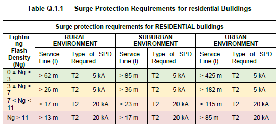
Note that the “Service Line” referred to above is the incoming (AC) line for the house.
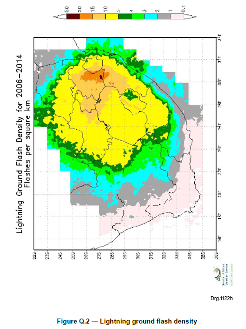
Here is a lightning density map for South Africa as provided in SANS 10142-1:
G2. SANS 60364-7-712 (2018) Low Voltage Electrical Installations: Requirements for special installations or locations – Solar photovoltaic (PV) power supply systems
Section 712.443.5.101 of SANS 60364-7-712 requires a Surge Protection Device to be installed on the DC side of the installation where the length (L) of the DC cables (from PV array to Elon® Smart or inverter) exceeds the critical length Lcrit as follows:
A Surge Protection Device is required where L ≥ Lcrit
The critical length Lcrit depends on the type of PV installation and is calculated according to the following table:
|
Type of installation |
Individual residential premises |
Terrestrial production plant |
Service / Industrial / Agricultural Buildings |
|
Lcrit (in meter) |
115/Ng |
200/Ng |
450/Ng |
where Ng = lightning strike density (number of strikes/km²/yr)
The length of DC cables L is the sum of:
- distances between the inverter(s) and the junction box(es), while observing that the lengths of cable located in the same conduit are counted only once, and
- distances between the junction box and the connection points of the photovoltaic modules forming the string, observing that the lengths of cable located in the same conduit are counted only once.
For the Elon® Smart, distance L is the length of DC cables from PV array to the Elon® Smart.
On the next page is a national lightning ground stroke density map for South Africa[5].
From this map, the lightning strike density (Ng) range for major cities are as follows:
|
City |
Lightning strike density Ng (strikes/km²/yr) |
Lcrit (m) |
|
|---|---|---|---|
|
Individual residential premises |
Service / industrial / agricultural buildings |
||
|
Cape Town |
0.02 to 4 |
29 |
113 |
|
Stellenbosch |
0.02 to 4 |
29 |
113 |
|
Worcester |
0.02 to 4 |
29 |
113 |
|
George |
0.02 to 4 |
29 |
113 |
|
Saldanha |
0.02 to 4 |
29 |
113 |
|
Gqeberha (Port Elizabeth) |
0.02 to 4 |
29 |
113 |
|
Buffalo City (East London) |
4 to 6 |
19 |
75 |
|
King Williams Town |
4 to 6 |
19 |
75 |
|
Beaufort-West |
4 to 6 |
19 |
75 |
|
Musina |
4 to 6 |
19 |
75 |
|
Britstown |
6 to 15 |
8 |
30 |
|
Durban |
6 to 15 |
8 |
30 |
|
Upington |
6 to 15 |
8 |
30 |
|
Pietermaritzburg |
15 to 21 |
5 |
21 |
|
Greytown |
15 to 21 |
5 |
21 |
|
Polokwane |
15 to 21 |
5 |
21 |
|
Bloemfontein |
15 to 21 |
5 |
21 |
|
Queenstown |
15 to 21 |
5 |
21 |
|
Vryburg |
15 to 21 |
5 |
21 |
|
Mahikeng |
15 to 21 |
5 |
21 |
|
Mbombela (Nelspruit) |
15 to 21 |
5 |
21 |
|
Kimberley |
21 to 27 |
4 |
16 |
|
Pretoria |
21 to 27 |
4 |
16 |
|
Vereeniging |
21 to 27 |
4 |
16 |
|
Welkom |
21 to 27 |
4 |
16 |
|
Johannesburg |
27 to 33 |
3.5 |
13 |
|
Ermelo |
33 to 42 |
2.5 |
10 |
|
Newcastle |
33 to 42 |
2.5 |
10 |
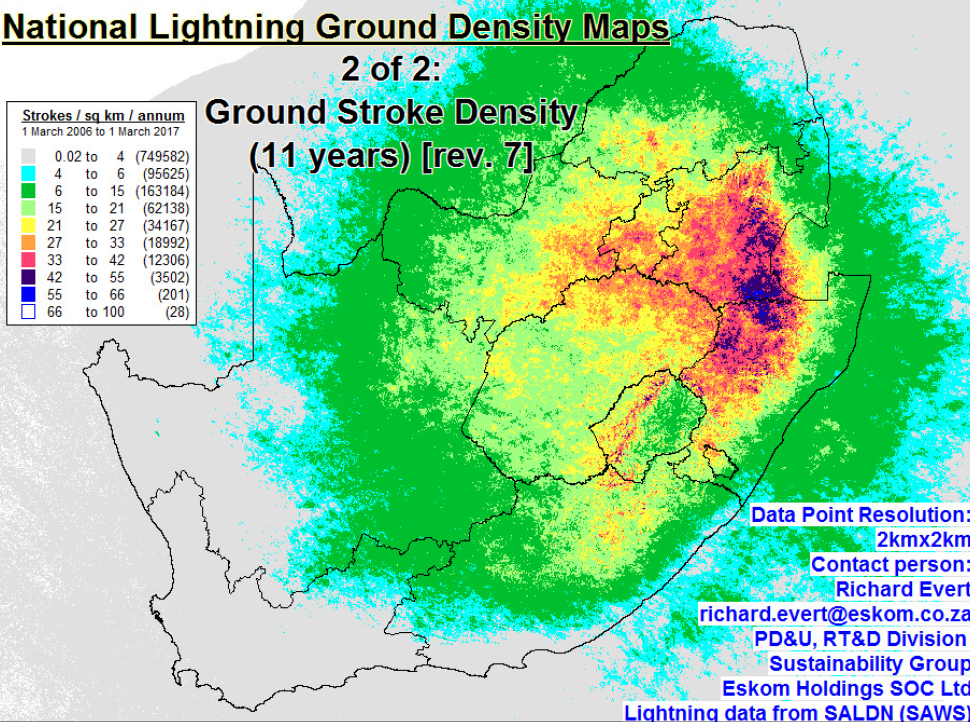
From Evert & Gijben (2017).
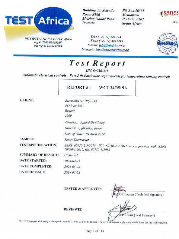
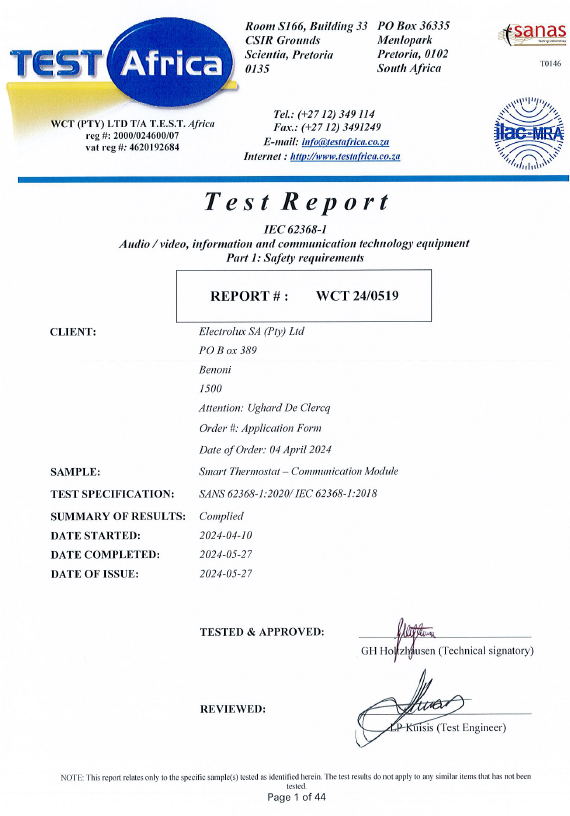
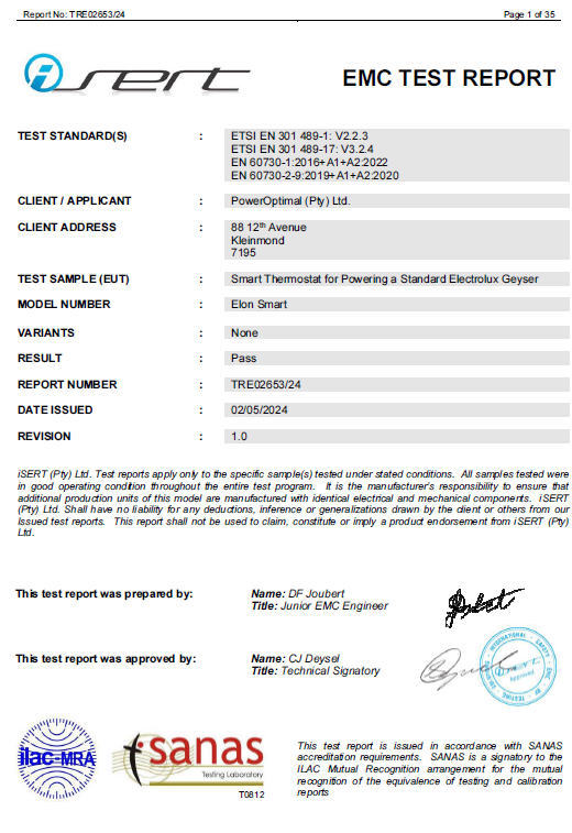
Appendix H. IEC/SANS and EMC Test Certificates: Elon® Smart
Appendix I. Warranty
If the PowerOptimal Elon® Smart (“the Product”) is found to be defective, you will be entitled to a repair or replacement within 2 (two) year of the date of delivery of the Product to you. Please keep your receipt as proof of purchase or register the Elon Smart online. If you are a consumer as defined in the Consumer Protection Act No. 68 of 2008 (“the CPA”), you will be entitled to such remedies as are made available under the CPA in relation to the return of goods.
PowerOptimal will not have any liability or obligation to you where the Product has been subjected to abuse, misuse, improper use, improper testing, negligence, accident, alteration, tampering or repair by a third party.
To the maximum extent permitted by applicable law, in no event shall PowerOptimal be liable for any special, incidental, indirect, or consequential damages whatsoever, including, without limitation, damages for loss of business profits or business interruption, arising out of the use or inability to use this product.
Please note that this unit must be installed by an electrical contractor registered with the Department of Labour. Failure to do so may invalidate this warranty. Please keep the CoC (Certificate of Compliance) issued by the electrical contractor on completion of the installation.
Register your Elon Smart online to get an extended 5-year warranty here:
https://poweroptimal.com/elon-extended-warranty/
Appendix J. Terminology
AC Alternating Current – an electric current that reverses its direction many times a second at regular intervals, with voltage typically varying in the form of a sine wave.
CoC Certificate of Compliance – to be issued by the electrician installing your Elon® Smart system
CPA Consumer Protection Act No. 68 of 2008
DB Distribution board – the main electrical distribution board / panel in your home, containing circuit breakers and switches.
DC Direct Current – an electric current flowing in one direction only. Solar PV modules produce direct current electricity.
Geyser South African term for a water heater
IEC International Electrotechnical Commission
Impp The solar module current at maximum power point (MPP). Manufacturers usually report two Impp values: one at STC and one at NOCT.
kWh A derived unit of energy equal to 3.6 MJ (megajoules). The amount of energy used by a 1 kW electrical device over a period of 1 hour.
kWp or Wp The peak power rating in kilowatt (kW) or watt (W) of a solar module or array – i.e., the output power achieved under full solar radiation. This is usually reported at STC and NOCT.
MPP Maximum power point. This is the point on a solar cell, module or array’s power or I-V (current-voltage) curve that has the highest power output.
NOCT Nominal Operating Cell Temperature (also sometimes referred to as NMOT or Nominal Module Operating Temperature). This refers to the temperature that open circuited solar PV modules will reach under conditions that more closely match actual field operational conditions than STC. The modules are tested at 800 W/m² simulated solar irradiance, 20 °C ambient temperature, 1 m/s wind velocity and open back side mounting. Depending on the quality of the cell / module design, the NOCT can reach anything from 33 to 58 °C[6]. Since solar PV cell power output reduces with increase in temperature, a lower NOCT is better.
PV Photovoltaic – referring to the production of electric current at the junction of two materials exposed to light.
SANS South African National Standards
STC Standard Test Conditions for solar cells – 1000 W/m² simulated solar irradiance and 25 °C solar cell temperature, and an air mass 1.5 spectrum (AM1.5).
Vmpp The solar module voltage at maximum power point (MPP). Manufacturers usually report two Vmpp values: one at STC and one at NOCT.
Notes
-
CRSES (Centre for Renewable and Sustainable Energy Studies). Website: http://www.crses.sun.ac.za/files/research/publications/SolarGIS_GHI_South_Africa_width15cm_300dpi.png. Last accessed: 07/04/2017. ↑
-
Urban Energy Support. Website: http://www.cityenergy.org.za/uploads/resource_274.pdf. Last accessed: 07/04/2017. ↑
-
D’Orazio M et al. 2013. Performance assessment of different roof integrated photovoltaic modules under Mediterranean Climate. ↑
-
Image source: http://ohioline.osu.edu/factsheet/AEX-652-11. ↑
-
Evert CR, Gijben M. 2017. Official South African Lightning Ground Flash Density Map 2006 to 2017. ↑
-
Source: http://pveducation.org/pvcdrom/modules/nominal-operating-cell-temperature. ↑