PowerOptimal Elon® 100 Installation Manual v2.30


PowerOptimal Elon® 100 Installation Manual
Version date: 2025/12/28
Enquiries: [email protected]
Address: Postnet Suite 21
Private Bag X21
Tyger Valley
7536
Please note: Always check the PowerOptimal website for the latest version of this manual.
Patented: ZA2019/02129

SAFETY WARNING
- Installation of the Elon® 100 should ONLY be performed by an electrical contractor registered with the Department of Labour (the so-called “wireman’s licence”) and strictly according to the installation instructions in this manual. The electrician should provide you with a supplementary Certificate of Compliance (CoC) once installation is completed.
- We strongly recommend that you use a reputable and experienced solar photovoltaic (PV) system installer to install your solar PV modules.
- Solar PV modules exposed to the sun are live (i.e. will produce electricity) and can give an electric shock. Special care should be taken and only trained solar PV installers should install the modules.
- Do not attempt to alter or service the electrical installation, or open the Elon® 100 unit or controller for any purpose.
- Use the Elon® 100 only for its intended purpose.
- Always make sure that every wiring connection is properly tightened.
- Do not earth either of the solar module wires (but do earth the frames).
- All installation wiring should be at least 2.5mm².
- Avoid coiling, since DC switching can create damaging spikes.
- Keep all wires as short as possible.
Refer to the PowerOptimal website for the following:
| |
| |
| |
|
 Elon® 100 User Manual
 Training videos for electricians
  Online User Instructions Video
 Online Elon® Basic Training Course
Table of Contents
Table of Contents 3
1. Required tools 4
2. Basic wiring diagram 5
3. Solar PV array installation 8
4. Elon® 100 installation 10
5. Element installation (retrofit) 18
Appendix A. Basic Troubleshooting Guide for Electricians 20
Appendix B. Solar yield 21
B1. Solar irradiance levels 21
B2. Geographic features 22
B3. Azimuth / horizontal angle 22
B4. Inclination or tilt angle 22
B5. Shading 22
B6. Ambient temperature 23
B7. Minimum distance from roof edges 23
Appendix C. Deciding on Size of Solar Array 24
Appendix D. PV array and geyser (water heater) element matching 28
Appendix E. Technical Specification Summary: Elon® 100 29
Appendix F. Surge Protection Device (SPD) Recommendations 30
F1. SANS 10142-1 The wiring of premises Part 1: Low-voltage installations 30
F2. Draft standard SANS 10142-3 Proposed Interim Guideline for the wiring of LV grid-embedded PV installations not exceeding 1000kVA in South Africa 31
Appendix G. IEC/SANS and EMC Test Certificates: Elon® 100 34
Appendix H. Warranty 39
Appendix I. Terminology 40
Notes 41
1. Required tools
The following tools are required for the installation. Use insulated tools wherever applicable.
- Solar modules (mounting) - please refer to solar module / mounting installation instructions – the below is only a guideline:
- Cordless screwdriver with bits
- Drill
- Set of drill bits (wood, steel, stone)
- Set of screwdrivers
- Set of Allen (hex) keys
- Tape measure
- Grinder (tile roof installations)
- Permanent marker
- Chalk
- Hammer
- Solar modules (electrical):
- AC/DC Clamp meter
- Side-cutting pliers
- Screwdriver set
- Crimping tool
- 4 mm² wire (double insulated) (or other size as determined by solar PV voltage and wire length)
- Cable ties
- Elon® 100 - the following additional tools:
- 2.5 mm² panel wire
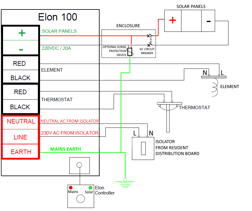
2. Basic wiring diagram
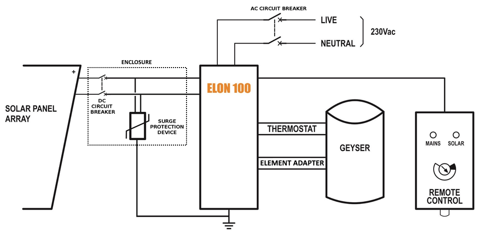
Note 1: Both AC & DC circuit breakers or isolators must be installed within 1.5m of the geyser (water heater), line of sight.
Note 2: Surge Protection Device (SPD) only required in higher lightning strike density areas (such as parts of Gauteng and Mpumalanga), or where the DC cables are long. See Appendix F.