Elon 100 documents
Brochures, specifications, installation manuals, and troubleshooting guides.
- Brochures
- PowerOptimal Elon 100 - how to maximise your savings
- PowerOptimal Elon® 100 brochure V2.13
- PowerOptimal Elon® 100 kit easy selection guide V2.13
- Product Specifications
- Installation & User Manuals
- PowerOptimal Elon® 100 Quick Reference User Guide v2.08
- PowerOptimal Elon® 100 User Manual v2.20
- PowerOptimal Elon® 100 Installation Manual v2.30
- PowerOptimal Elon 100 Installation Manual v1.40 (Elon 100 units pre-2019)
- PowerOptimal Elon 100 User Manual v1.40 (Elon 100 units pre-2019)
- PowerOptimal Elon® 100 Commissioning Checklist V1.02
- PowerOptimal Elon® 100 Installation Checklist V1.03
- Troubleshooting Guides
Brochures
PowerOptimal Elon 100 - how to maximise your savings
How can you Maximise Your Savings with the Elon 100 Solar PV Water Heater?
The Elon 100® solar PV water heater will help you save money on the biggest single electricity user in your household: your geyser.

Here are some tips for maximising your savings:
- The best way to maximise your savings is to set the Elon® control dial to “SOLAR ONLY”. This will ensure that the unit will never use grid (mains) power for heating water. You can still boost with mains power (for example on a cloudy day) by turning the dial to "MAINS ONLY" if needed. (Turn the dial to “MAINS ONLY” until the red light starts flashing, then turn it back to “SOLAR ONLY”. It will complete one heating cycle with grid and then go back to using solar power only.)
However, the "SOLAR ONLY" setting will only be feasible if you have enough solar PV modules for your household’s level of hot water use. Even if you have a smaller system, you might be able to run it on “SOLAR ONLY” for most of the year, depending on your location.
- If “SOLAR ONLY” doesn’t work for your household, setting the dial at "3" will yield the most savings whilst maintaining hot water availability mornings and evenings.
- Install water-saving (low-flow) showerheads. This can reduce your hot water use by 20 to 40%. (You will also save on your water bill!)
- Shower, don’t bath;
- Reduce shower duration;
- Check that your geyser is well insulated;
- It is generally best to shower in the mornings for maximum savings, since then the water can be reheated during the day. (If you have the control dial on “SOLAR ONLY”, you can alternatively shower only in the evenings, as long as you remember that you won’t have hot water early in the morning.)
- A bigger geyser (200L vs 150L or 100L) is better for maximising savings, since more energy from the sun can be stored in the bigger volume of water.
See this video for more on how to use the Elon 100 solar PV water heater.
PowerOptimal Elon® 100 brochure V2.13
V2.13
The PowerOptimal Elon® The Most Cost-Effective Solar Water Heating Solution

Conventional wisdom has it that solar thermal is the most cost-effective solar water heating solution. Well, it is time to update conventional wisdom! The innovative and patent-pending PowerOptimal Elon® breaks the mould in bringing solar PV (photovoltaic) and water heating together in the most cost-effective package ever. Meeting national building regulations on water heating is now made easy with the PowerOptimal Elon®.
With competitive capital cost, very long lifetimes and almost non-existent maintenance, this is the lowest cost per kWh of water heating your money can buy anywhere.
HOW IT WORKS
The Elon® uses advanced proprietary switching technology to allow for direct provision of DC (Direct Current) power from solar PV (photovoltaic) modules to electric geyser and optimised solar power use in a single compact unit. The system can be connected to the grid (AC mains) as well, and intelligently switches between AC and solar power supply. The system requires no inverter and no battery, and can be connected to standard AC geyser heating elements and AC thermostats, which translates into the most cost-effective solar water heating option today.

WHAT ARE THE BENEFITS?
Based on a lifetime cost per kWh of water heating (Levelised Cost of Energy or LCOE), the Elon® brings you the lowest cost of any water heating option in South Africa at about R1.15/kWh. The average residential price of electricity in South Africa in 2024 (based on a middle-class household in the four largest metropolitan areas) is about R3.12/kWh and increases every year. Reduce your exposure to ever-increasing electricity prices by installing an Elon® system.

There are many other benefits to the PowerOptimal Elon® solar PV water heating system:
|
|
WHAT DOES THE SAVINGS TRANSLATE TO IN PRACTICAL TERMS?
Below is a comparison of the energy cost per shower for various energy supply options.

WHO IS POWEROPTIMAL?

PowerOptimal is an award-winning company with a mission to bring affordable, reliable and sustainable energy solutions to households and businesses across the African continent. The company is built on proven South African electricity demand management technology, with a strong track record of successful installations over more than 10 years.
FAQ – Frequently Asked Questions
How can solar PV water heating be more cost-effective than solar thermal? Isn’t solar thermal efficiency much better than solar PV?
It is true that solar thermal collectors are currently more efficient per square meter (area) than solar PV modules in collecting solar energy. However, overall efficiency must also take into consideration factors such as heat loss in piping (especially in winter) and energy use of solar thermal circulation pumps.
Solar thermal system lifetimes range from about 7 years (for cheap imports) to about 15 years for high quality (and more expensive) systems. (In a comprehensive analysis, Sandia National Laboratories found that about 50% of solar thermal systems fail within a 10-year period.) Solar PV modules are routinely guaranteed at 80% performance after 25 years, and the US National Renewable Energy Laboratory uses a lifetime of 33 years in its solar PV system calculations.
Solar PV module costs have dropped dramatically – by over 80% in the past 5 years – and the trend is continuing. This has changed the paradigm. Whilst solar PV systems will continue to require more roof space than solar thermal in the short term, the key issue is not roof space, but cost. Solar PV systems have become cost-competitive to solar thermal, and the much longer lifetimes and lower maintenance translate into a lower lifetime cost per kWh.
What is SANS 10400-XA?
It is a set of energy efficiency regulations that are compulsory for new buildings and for additions and extensions to existing buildings. One of the key requirements of SANS 10400-XA is that no more than 50% of the annual volume of domestic hot water must be heated using grid electricity.
The PowerOptimal Elon® makes meeting this requirement easier than ever before, providing a new cost-effective alternative to heat pump and solar thermal systems.
Do I need to change the heating element on my existing geyser to install a PowerOptimal Elon® system?
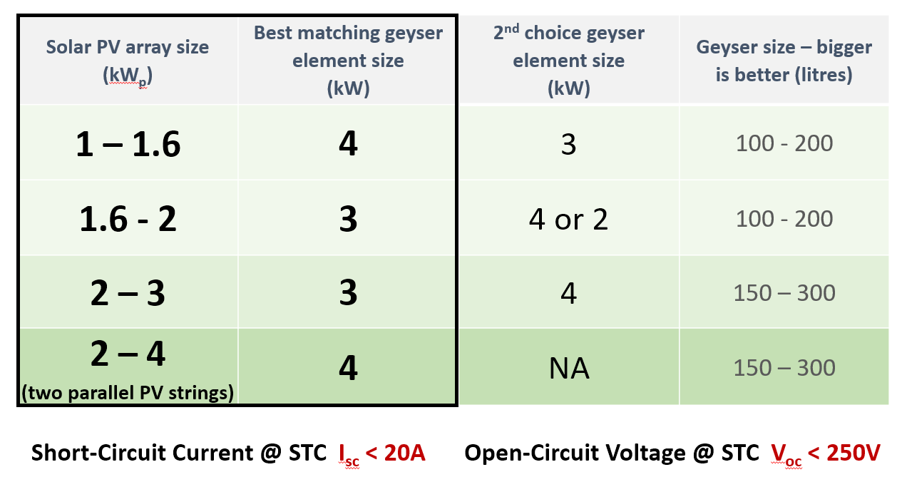
Not necessarily. PowerOptimal Elon® works with existing standard AC heater elements, but the best element size (power rating) depends on the size of your solar PV array. If you are building a new house, you can just specify the right heater element from the start. Refer to the table on the next page for a guide or ask the PowerOptimal agent or your installer about the best module & element matching configuration for your needs.
![]()
Where can I buy an Elon® system?
For installers and resellers: Kwikot (part of Electrolux South Africa) is the sole distributor of the PowerOptimal Elon® in South Africa. Contact the PowerOptimal team for assistance with buying.
For residential customers: Contact PowerOptimal to get a referral to one of our preferred installers depending on your location.
How many solar modules do I need?
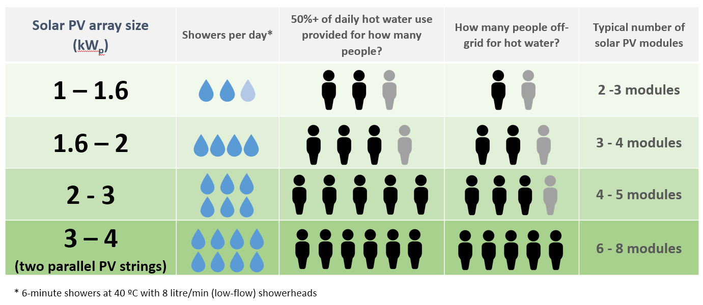
The most important factor here is the total size or power of the solar PV array (measured in kilowatt or kWp) rather than the number of modules. The size of solar PV array required depends on the number of people in the household and your hot water usage levels. A minimum of 1 kWp is recommended. Below is an easy selection guide. Refer to the PowerOptimal Elon® 100 Technical Specifications or the full selection guide (available on the downloads page) for a more detailed guide.

* 6-minute showers at 40 ºC with 8 litre/min (low-flow) showerheads
What is the payback period for an Elon® system?
This depends on your current electricity tariff, how many solar modules you install, your hot water use, and electricity price increases in the next few years, but typically payback period is in the range of 2½ to 5 years. With a typical solar module life expectancy of more than 30 years, this means that you will enjoy at least 25 years of free hot water!
Where can I learn more about the PowerOptimal Elon®?
Visit our website at www.poweroptimal.com or contact the PowerOptimal team for more information and technical data sheets.
CONTACT US TODAY TO GET A QUOTE OR LEARN MORE ABOUT THE POWEROPTIMAL ELON®

Patented: GB2583814, ZA2019/02129
PowerOptimal contact page: https://poweroptimal.com/contact-us/
PowerOptimal Elon® 100 kit easy selection guide V2.13
Elon® 100 kit easy selection guide: element matching
Elon® 100 kit easy selection guide: how much hot water?
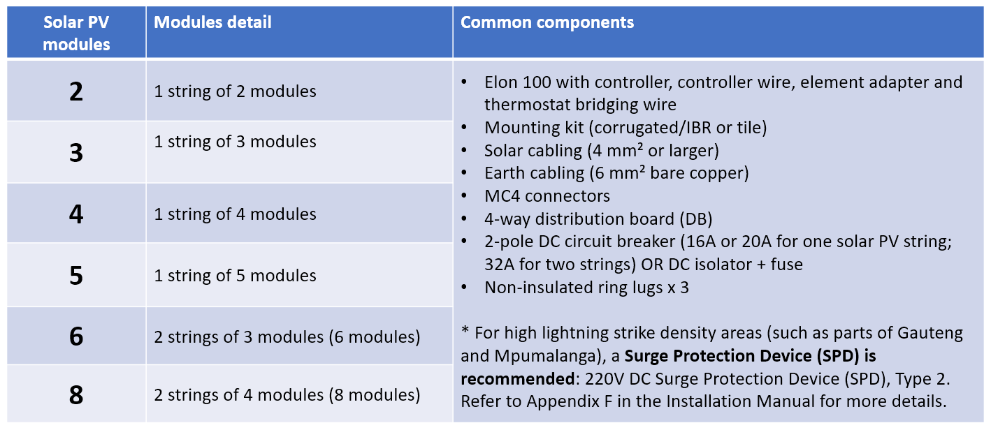
Typical kit contents
Product Specifications
PowerOptimal Elon® 100 specification V2.20
INTRODUCING THE
PowerOptimal Elon® 100
The innovative PowerOptimal Elon® 100 incorporates proprietary solar PV (photovoltaic) power management technology to allow for direct connection of solar PV arrays to electric geysers (water heaters) with optimised solar power use in a single compact unit. The system can be connected to the grid (AC mains) as well, and intelligently switches between AC and solar power supply. The system requires no inverter and no battery. It can be connected to standard AC geyser heating elements and AC thermostats, which translates into the most cost-effective solar water heating option today.
Document Version: 2.20
SPECIFICATIONS
|
Rated input voltage |
250V AC, 250V DC |
|
Rated input current |
25A AC, 20A DC |
|
Mains (AC) voltage range (over-voltage & undervoltage protection) |
-50% to +100%. Overvoltage protection up to 500V and undervoltage protection down to 125V. Will disconnect all loads when breach is greater than +/- 15%. |
|
System power supply |
Solar or 230V AC mains |
|
Power consumption |
<3W on mains power; <0.5W on solar power |
|
Shutdown |
Sufficient power supply capacity to manage processor, switching and data storage if both mains and solar supply fail |
|
Solar voltage (Voc at STC) |
20 – 250 V DC |
|
Solar power availability sensing |
Automatically determines availability of sufficient solar power before supplying load from solar PV array |
|
Controller settings |
Can be adjusted to run from “solar only” (100% solar energy use) to “mains only” (no solar energy use) with 3 settings in between to allocate different proportions of the day to solar and mains. |
|
Thermostat |
Uses the standard thermostat switch associated with the geyser element as a sensor only, with less than 10mA sense current, to control power to the element |
|
Reverse polarity protection |
Protected against reverse connection of solar array |
|
Enclosure ingress protection rating |
Elon 100 main unit: IP65 Elon 100 remote control: IP40 (install indoors or in waterproof enclosure) |
|
Max. distance Elon® unit to controller |
10 m (can be extended) |
|
Annual energy production compared to inverter-based system |
> 90% when solar array and geyser element are matched correctly |
|
Standards conformance |
IEC / SANS 60669-1, 60669-2-1, 60730-1, 60335-1, 60335-2-21, CISPR 11 & IEC 61000-6-1 |
|
Dimensions & weight |
Elon® 100 main unit: 200 x 150 x 90 mm (LxWxH), 1.75 kg. Controller: 50 x 72 x 41 mm (LxWxH) Box information (for shipping): 230 x 150 x 150 mm (LxWxH), 2 kg. |
|
Patents |
ZA 2019/02129 |
It is important to match the solar PV array and heating elements for maximum power transfer efficiency. See Table 1B for the recommended AC heating element power rating for different solar panel specifications and configurations.
Contact PowerOptimal for advice on module-element matching if module properties are significantly different to typical values or for bifacial, high current or high voltage modules.
TABLE 1A. ELON® KIT EASY SELECTION GUIDE – HOW MANY SOLAR PV MODULES DO I NEED?
The below table provides an easy selection guide based on number of people in the household and/or hot water use (showers/day). Minimum recommended array size is 1 kWp. More detailed information and selection guidelines are provided in Tables 2-7.
TABLE 1B. ELON® KIT EASY SELECTION GUIDE – WHAT SIZE GEYSER ELEMENT IS THE BEST MATCH?
To get the best performance from your Elon® solar PV water heater, it is important that the geyser element is a good match for the size of your solar PV array. This table helps you match the size of the solar PV array with the size of the geyser element.
TABLE 2. ANNUAL AVERAGE LITRES OF WATER HEATED PER DAY
The below example table indicates the average number of litres of water per day that the system will heat from 15 to 60 °C over a year period for different solar array peak power ratings. (The amount of water heated will vary with weather conditions, by geographic location and by season. Water heated per day will be significantly lower in winter and significantly higher in summer. These numbers indicate heating capacity – i.e. if no hot water is used on a given day, there will be less water heated on that day. This is only an approximate guide.)
|
|
Solar + Elon® |
Annual average litres of water heated per day for X kWp installed solar capacity |
|||||||||
|
Location |
kWh/kWp/yr |
0.8 kWp |
1 kWp |
1.2 kWp |
1.4 kWp |
1.6 kWp |
1.8 kWp |
2 kWp |
2.5 kWp |
3 kWp |
3.5 kWp |
|
Bloemfontein |
1894 |
80 |
99 |
119 |
139 |
159 |
179 |
199 |
249 |
298 |
348 |
|
Cape Town |
1624 |
68 |
85 |
102 |
119 |
136 |
154 |
171 |
213 |
256 |
299 |
|
Durban |
1447 |
61 |
76 |
91 |
106 |
122 |
137 |
152 |
190 |
228 |
266 |
|
Jhb/Pretoria |
1724 |
72 |
91 |
109 |
127 |
145 |
163 |
181 |
226 |
272 |
317 |
|
Mbombela |
1627 |
68 |
85 |
103 |
120 |
137 |
154 |
171 |
214 |
256 |
299 |
|
Port Elizabeth |
1565 |
66 |
82 |
99 |
115 |
132 |
148 |
164 |
205 |
247 |
288 |
|
Upington |
1912 |
80 |
100 |
121 |
141 |
161 |
181 |
201 |
251 |
301 |
352 |
|
Saldanha |
1623 |
68 |
85 |
102 |
119 |
136 |
153 |
170 |
213 |
256 |
298 |
Example:
For a solar PV array of 1.2 kWp, an installation in Johannesburg would yield about 1724 kWh/kWp/yr, or 1724 x 1.2 kWp = 2069 kWh/yr. This would be sufficient to heat on average 109 litres of water per day. For a family of 2 each using 80 litres of hot water per day, this would provide about 109 ÷ (80 x 2) or 68% of the annual hot water requirement.
TABLE 3. ANNUAL AVERAGE NUMBER OF SHOWERS PER DAY
The below table indicates the average number of showers per day for which the system will supply hot water over a year period for different solar array peak power ratings. (The amount of water heated will vary with weather conditions, by geographic location and by season. Water heated per day will be significantly lower in winter and significantly higher in summer. These numbers indicate heating capacity – i.e. if no hot water is used on a given day, there will be less water heated on that day. This is only an approximate guide.)
|
|
Solar + Elon® |
Number of showers per day (based on annual average) for X kWp installed solar capacity |
|||||||||
|
Location |
kWh/kWp/yr |
0.8 kWp |
1 kWp |
1.2 kWp |
1.4 kWp |
1.6 kWp |
1.8 kWp |
2 kWp |
2.5 kWp |
3 kWp |
3.5 kWp |
|
Bloemfontein |
1894 |
2.4 |
3.0 |
3.6 |
4.2 |
4.8 |
5.4 |
6.0 |
7.5 |
9.0 |
10.4 |
|
Cape Town |
1624 |
2.0 |
2.6 |
3.1 |
3.6 |
4.1 |
4.6 |
5.1 |
6.4 |
7.7 |
9.0 |
|
Durban |
1447 |
1.8 |
2.3 |
2.7 |
3.2 |
3.6 |
4.1 |
4.6 |
5.7 |
6.8 |
8.0 |
|
Jhb/Pretoria |
1724 |
2.2 |
2.7 |
3.3 |
3.8 |
4.3 |
4.9 |
5.4 |
6.8 |
8.2 |
9.5 |
|
Mbombela |
1627 |
2.1 |
2.6 |
3.1 |
3.6 |
4.1 |
4.6 |
5.1 |
6.4 |
7.7 |
9.0 |
|
Port Elizabeth |
1565 |
2.0 |
2.5 |
3.0 |
3.5 |
3.9 |
4.4 |
4.9 |
6.2 |
7.4 |
8.6 |
|
Upington |
1912 |
2.4 |
3.0 |
3.6 |
4.2 |
4.8 |
5.4 |
6.0 |
7.5 |
9.0 |
10.5 |
|
Saldanha |
1623 |
2.0 |
2.6 |
3.1 |
3.6 |
4.1 |
4.6 |
5.1 |
6.4 |
7.7 |
9.0 |
The table is based on 6-minute showers at 40 °C and 8 litres/min low flow showerheads. Old showerheads can use up to 15 litres/min and would substantially reduce the number of showers.
Example:
For a solar PV array of 2.5 kWp, an installation in Johannesburg would yield about 1724 kWh/kWp/yr, or 1724 x 2.5 kWp = 4 310 kWh/yr. This would be sufficient for about 6 to 7 showers per day.
TABLE 4. PERCENTAGE OF ANNUAL HOT WATER REQUIREMENT
The below example table indicates what % of the annual hot water requirement will on average be supplied by the system for 2 people each using 80 litres of hot (60 °C) water per day. (The amount of water heated will vary with weather conditions, by geographic location and by season. Water heated per day will be significantly lower in winter and significantly higher in summer. These numbers indicate heating capacity – i.e. if no hot water is used on a given day, there will be less water heated on that day. This is only an approximate guide.)
|
Solar + Elon® |
Annual average % of hot water requirement supplied for 2 people each using 80 litres of hot water per day for X kWp installed solar capacity |
||||||||||
|
Location |
kWh/kWp/yr |
0.8 kWp |
1 kWp |
1.2 kWp |
1.4 kWp |
1.6 kWp |
1.8 kWp |
2 kWp |
2.5 kWp |
3 kWp |
3.5 kWp |
|
Bloemfontein |
1894 |
50% |
62% |
75% |
87% |
99% |
112% |
124% |
155% |
187% |
218% |
|
Cape Town |
1624 |
43% |
53% |
64% |
75% |
85% |
96% |
107% |
133% |
160% |
187% |
|
Durban |
1447 |
38% |
47% |
57% |
66% |
76% |
85% |
95% |
119% |
142% |
166% |
|
Jhb/Pretoria |
1724 |
45% |
57% |
68% |
79% |
91% |
102% |
113% |
142% |
170% |
198% |
|
Nelspruit |
1627 |
43% |
53% |
64% |
75% |
85% |
96% |
107% |
134% |
160% |
187% |
|
Port Elizabeth |
1565 |
41% |
51% |
62% |
72% |
82% |
92% |
103% |
128% |
154% |
180% |
|
Upington |
1912 |
50% |
63% |
75% |
88% |
100% |
113% |
126% |
157% |
188% |
220% |
|
Saldanha |
1623 |
43% |
53% |
64% |
75% |
85% |
96% |
107% |
133% |
160% |
186% |
Examples:
An array of 1.2 kWp will provide approximately 64% of the annual hot water requirement for a family of two people in Cape Town.
An array of 2 kWp will provide approximately 124% x (2 / 4) = 62% of the annual hot water requirement for a family of four people in Bloemfontein.
TABLE 5. PEAK POWER OUTPUT FOR VARIOUS SOLAR MODULES AND ARRAY SIZES
The peak power production (Wp) of the modules at STC (Standard Test Conditions: irradiance 1000 W/m², spectrum AM 1.5, module temperature 25 °C) and at NOCT (Nominal Operating Cell Temperature, irradiance 800 W/m², spectrum AM 1.5, module temperature ~43 – 45 °C) are provided by the solar PV module manufacturer. The below table indicates the peak power at STC for a range of solar module power ratings and array sizes.
|
No. of cells per module |
Module STC power rating (Wp) |
Total peak power at STC in kWp for an array of X modules |
||||||
|---|---|---|---|---|---|---|---|---|
|
3 modules |
4 modules |
5 modules |
6 modules |
8 (2 x 4) modules |
10 (2 x 5) modules |
12 (2 x 6) modules |
||
|
60 or 120 |
265 |
0.795 |
1.06 |
1.325 |
1.59 |
2.12 |
2.65 |
3.18 |
|
60 or 120 |
270 |
0.81 |
1.08 |
1.35 |
1.62 |
2.16 |
2.70 |
3.24 |
|
60 or 120 |
275 |
0.825 |
1.10 |
1.375 |
1.65 |
2.20 |
2.75 |
3.30 |
|
60 or 120 |
280 |
0.84 |
1.12 |
1.40 |
1.68 |
2.24 |
2.80 |
3.36 |
|
60 or 120 |
285 |
0.855 |
1.14 |
1.425 |
1.71 |
2.28 |
2.85 |
3.42 |
|
60 or 120 |
290 |
0.87 |
1.16 |
1.45 |
1.74 |
2.32 |
2.90 |
3.48 |
|
60 or 120 |
295 |
0.885 |
1.18 |
1.475 |
1.77 |
2.36 |
2.95 |
3.54 |
|
60 or 120 |
300 |
0.90 |
1.20 |
1.50 |
1.80 |
2.40 |
3.00 |
3.60 |
|
60 or 120 |
305 |
0.915 |
1.22 |
1.525 |
1.83 |
2.44 |
3.05 |
3.66 |
|
60 or 120 |
310 |
0.93 |
1.24 |
1.55 |
1.86 |
2.48 |
3.1 |
3.72 |
|
60 or 120 |
315 |
0.945 |
1.26 |
1.575 |
1.89 |
2.52 |
3.15 |
3.78 |
|
60 or 120 |
320 |
0.96 |
1.28 |
1.6 |
1.92 |
2.56 |
3.2 |
3.84 |
|
60 or 120 |
325 |
0.975 |
1.3 |
1.625 |
1.95 |
2.6 |
3.25 |
3.9 |
|
60 or 120 |
330 |
0.99 |
1.32 |
1.65 |
1.98 |
2.64 |
3.3 |
3.96 |
|
72 or 144 |
310 |
0.93 |
1.24 |
1.55 |
1.86 |
2.48 |
3.10 |
3.72 |
|
72 or 144 |
315 |
0.945 |
1.26 |
1.575 |
1.89 |
2.52 |
3.15 |
3.78 |
|
72 or 144 |
320 |
0.96 |
1.28 |
1.60 |
1.92 |
2.56 |
3.20 |
3.84 NOT ALLOWED (exceeds maximum rated Elon® 100 voltage) |
|
72 or 144 |
325 |
0.975 |
1.30 |
1.625 |
1.95 |
2.60 |
3.25 |
3.90 |
|
72 or 144 |
330 |
0.99 |
1.32 |
1.65 |
1.98 |
2.64 |
3.30 |
3.96 |
|
72 or 144 |
335 |
1.005 |
1.34 |
1.675 |
2.01 |
2.68 |
3.35 |
4.02 |
|
72 or 144 |
340 |
1.02 |
1.36 |
1.70 NOT ALLOWED (exceeds maximum rated Elon® 100 voltage) |
2.04 |
2.72 |
3.40 |
4.08 |
|
72 or 144 |
345 |
1.035 |
1.38 |
1.725 |
2.07 |
2.76 |
3.45 |
4.14 |
|
72 or 144 |
350 |
1.05 |
1.40 |
1.75 |
2.10 |
2.80 |
3.50 |
4.20 |
|
72 or 144 |
355 |
1.065 |
1.42 |
1.775 |
2.13 |
2.84 |
3.55 |
4.26 |
|
72 or 144 |
360 |
1.08 |
1.44 |
1.8 |
2.16 |
2.88 |
3.6 |
4.32 |
|
72 or 144 |
365 |
1.095 |
1.46 |
1.825 |
2.19 |
2.92 |
3.65 |
4.38 |
|
72 or 144 |
370 |
1.11 |
1.48 |
1.85 |
2.22 |
2.96 |
3.7 |
4.44 |
|
72 or 144 |
375 |
1.125 |
1.5 |
1.875 |
2.25 |
3 |
3.75 |
4.5 |
|
72 or 144 |
380 |
1.14 |
1.52 |
1.9 |
2.28 |
3.04 |
3.8 |
4.56 |
|
72 or 144 |
385 |
1.155 |
1.54 |
1.925 |
2.31 |
3.08 |
3.85 |
4.62 |
|
72 or 144 |
390 |
1.17 |
1.56 |
1.95 |
2.34 |
3.12 |
3.9 |
4.68 |
|
72 or 144 |
395 |
1.185 |
1.58 |
1.975 |
2.37 |
3.16 |
3.95 |
4.74 |
|
72 or 144 |
400 |
1.2 |
1.6 |
2 |
2.4 |
3.2 |
4 |
4.8 |
|
72 or 144 |
405 |
1.215 |
1.62 |
2.025 |
2.43 |
3.24 |
4.05 |
4.86 |
|
72 or 144 |
410 |
1.23 |
1.64 |
2.05 |
2.46 |
3.28 |
4.1 |
4.92 |
|
72 or 144 |
415 |
1.245 |
1.66 |
2.075 |
2.49 NOT ALLOWED (exceeds maximum rated Elon® 100 voltage) |
3.32 |
4.15 |
4.98 |
|
72 or 144 |
420 |
1.26 |
1.68 |
2.1 |
2.52 |
3.36 |
4.2 |
5.04 NOT ALLOWED (exceeds maximum rated Elon® 100 voltage) |
|
72 or 144 |
425 |
1.275 |
1.7 |
2.125 |
2.55 |
3.4 |
4.25 |
5.1 |
|
72 or 144 |
430 |
1.29 |
1.72 |
2.15 |
2.58 |
3.44 |
4.3 NOT ALLOWED (exceeds maximum Elon® 100 power rating) |
5.16 |
|
72 or 144 |
435 |
1.305 |
1.74 |
2.175 |
2.61 |
3.48 |
4.35 |
5.22 |
|
72 or 144 |
440 |
1.32 |
1.76 |
2.2 |
2.64 |
3.52 |
4.4 |
5.28 |
|
72 or 144 |
445 |
1.335 |
1.78 |
2.225 |
2.67 |
3.56 |
4.45 |
5.34 |
|
72 or 144 |
450 |
1.35 |
1.8 |
2.25 |
2.7 |
3.6 |
4.5 |
5.4 |
|
72 or 144 |
455 |
1.365 |
1.82 |
2.275 |
2.73 |
3.64 |
4.55 |
5.46 |
Examples:
An array of 4 x 325 Wp modules in series will have a total peak power (at STC) of 1.3 kWp.
An array of 2 parallel strings of 5 modules of 280 Wp each (10 modules of 280 Wp in total) will have a total peak power (at STC) of 2.8 kWp.
Installation & User Manuals
PowerOptimal Elon® 100 Quick Reference User Guide v2.08
![]()
Online user instruction video: www.poweroptimal.com/elon100

Full user manual: www.poweroptimal.com/manuals
V 2.08
PowerOptimal Elon® 100 User Manual v2.20

PowerOptimal Elon® 100 User Manual
Version number: 2.20
Version date: 2025/12/28
Address: Postnet Suite 21, Private Bag X21, Tyger Valley, 7536
Patented: ZA2019/02129

SAFETY WARNING
- Installation of the Elon® 100 should ONLY be performed by an electrical contractor registered with the Department of Labour (the so-called “wireman’s licence”) and strictly according to the installation instructions in this manual. The electrician should provide you with a Certificate of Compliance (CoC) once installation is completed.
- We strongly recommend that you use a reputable and experienced solar photovoltaic (PV) system installer to install your solar PV modules.
- Solar PV modules exposed to the sun are live (i.e. will produce electricity) and can give an electric shock. Special care should be taken and only trained solar PV installers should install the modules.
- Do not attempt to alter or service the electrical installation, or open the Elon® 100 unit or controller for any purpose.
- Use the Elon® 100 only for its intended purpose.
- Always make sure that every wiring connection is properly tightened.
- Do not earth either of the solar module wires (but do earth the frames).
- All installation wiring should be at least 2.5mm².
- Avoid coiling, since DC switching can create damaging spikes.
- Keep all wires as short as possible.
Refer to the PowerOptimal website for the following:
|
|
|
|
|
|
|
|
 Online Elon® Basic Training Course
Table of Contents
1.3 Deciding on size of Elon® system (basic guide)
2.2 Mains and solar indicator lights
2.5 How to maximise your savings
3.1 Solar PV module maintenance
4. What to expect in terms of performance
4.2 Impact of location and seasons
5.1 Troubleshooting Guide for Users
5.2 Troubleshooting Guide for Electricians
Appendix A. IEC/SANS and EMC Test Certificates: Elon® 100
1. Introduction
Thank you for buying the PowerOptimal Elon® 100 solar PV water heating unit! You can look forward to many years of savings and free energy from the sun.
1.1 System overview
The PowerOptimal Elon® 100 operates on a very simple principle: it enables you to connect solar PV modules directly to a standard geyser with alternating current (AC) heating element and AC thermostat, with no need for an inverter. It uses the water in your geyser as a battery to store solar energy in the form of heat.
You can connect the system completely off-grid or connect it to your existing grid AC power supply. Connecting the system to the existing grid supply allows for grid power backup in case of cloudy / overcast days, or where you use more hot water than your solar PV array can generate.
Note: the system is designed in such a way that there is no possibility of solar array-produced electricity feeding back into the grid. For municipal registration purposes it is classified as "off-grid".
Below is a simplified layout of the main components of the water heating system.

An array of solar modules (a string of 3 to 6 solar modules connected in series, or two parallel strings of 4, 5 or 6 solar modules each) is connected to the Elon® 100. Grid electricity is also connected to the Elon® 100.
The Elon® 100 is connected to the geyser element and thermostat.
When the solar modules are producing electricity, the Elon® 100 feeds this into the geyser element to heat water, until the water reaches the temperature setting on the thermostat.
The Elon® 100 controller dial setting (see Section 2.3) will determine if or when the Elon® 100 will boost the water heating with grid electricity.
1.2 Main system components
The main components of the system are as follows:
- Solar modules with struts, brackets and cabling
- PowerOptimal Elon® unit with controller
- Existing or new water heater or geyser (hot water tank with AC heating element and AC thermostat)
- Isolators for grid and solar connections
1.3 Deciding on size of Elon® system (basic guide)
The table below provides a basic guide to selecting the size of your Elon® system based on number of people in the household and/or hot water use. The Installation Manual (which you can download from www.poweroptimal.com/manuals) contains a more detailed guide.
HOW MANY SOLAR PV MODULES DO I NEED?
WHAT SIZE GEYSER ELEMENT IS THE BEST MATCH?
2. Operation
Refer to our easy-to-understand instruction video on how to use the Elon 100.
![]() Instruction video: www.poweroptimal.com/elon100
Instruction video: www.poweroptimal.com/elon100
2.1 Elon® 100 controller
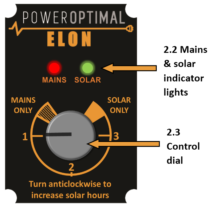
Your Elon® 100 has a controller that is typically installed next to your DB (distribution board). The controller has two main functions:
1. INDICATING ACTIVITY AND STATUS:
Indicating heating activity and status through the mains (red) & solar (green) indicator lights (Section 2.2)
2. CONTROL TIMING:
Setting the timing on the control dial (Section 2.3)
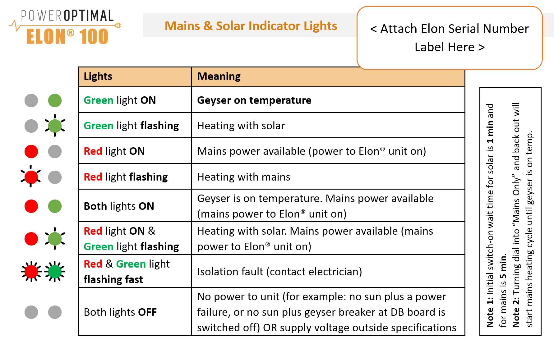
2.2 Mains and solar indicator lights
The Mains & solar indicator lights indicate the following conditions:
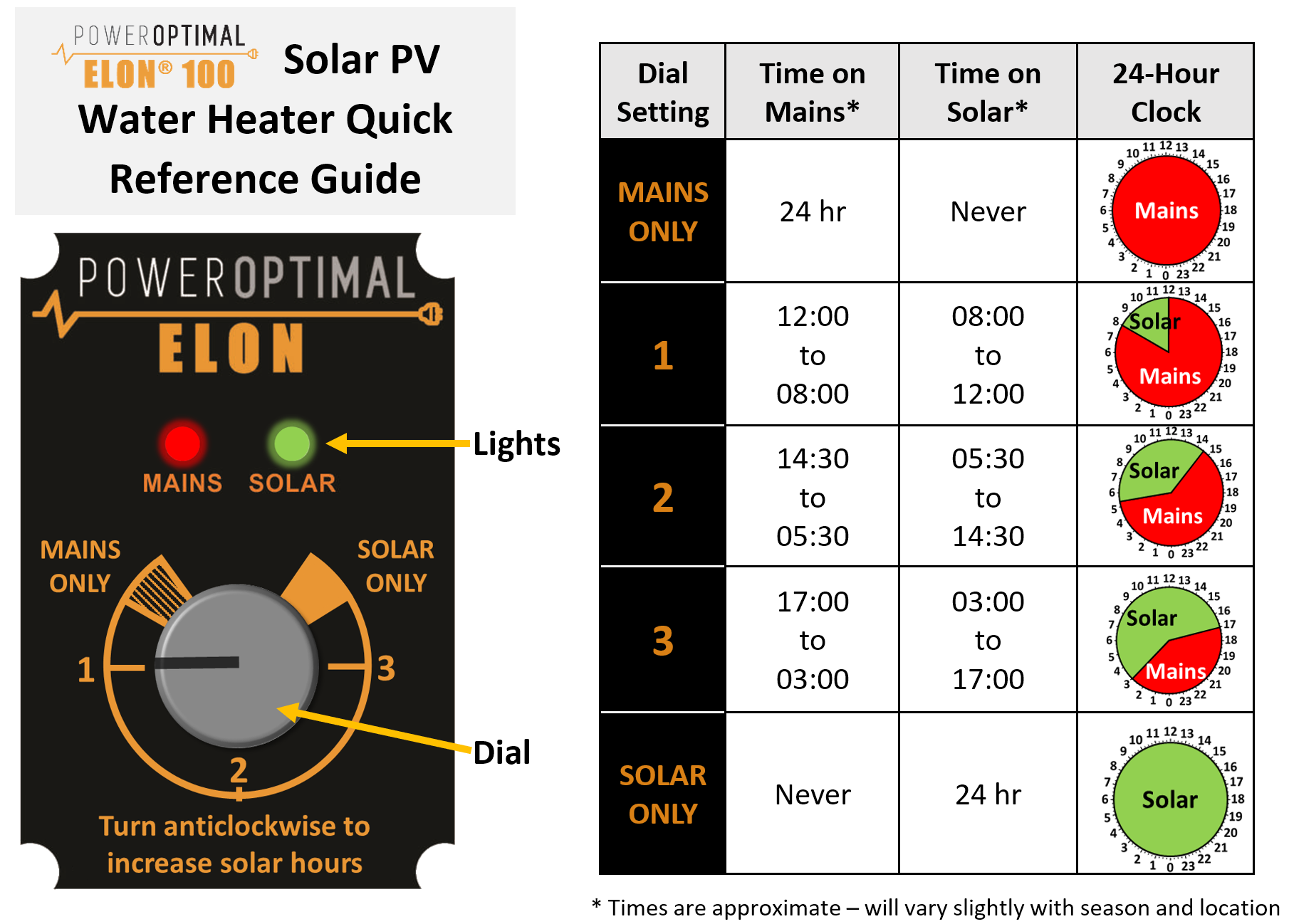
2.3 Control dial settings
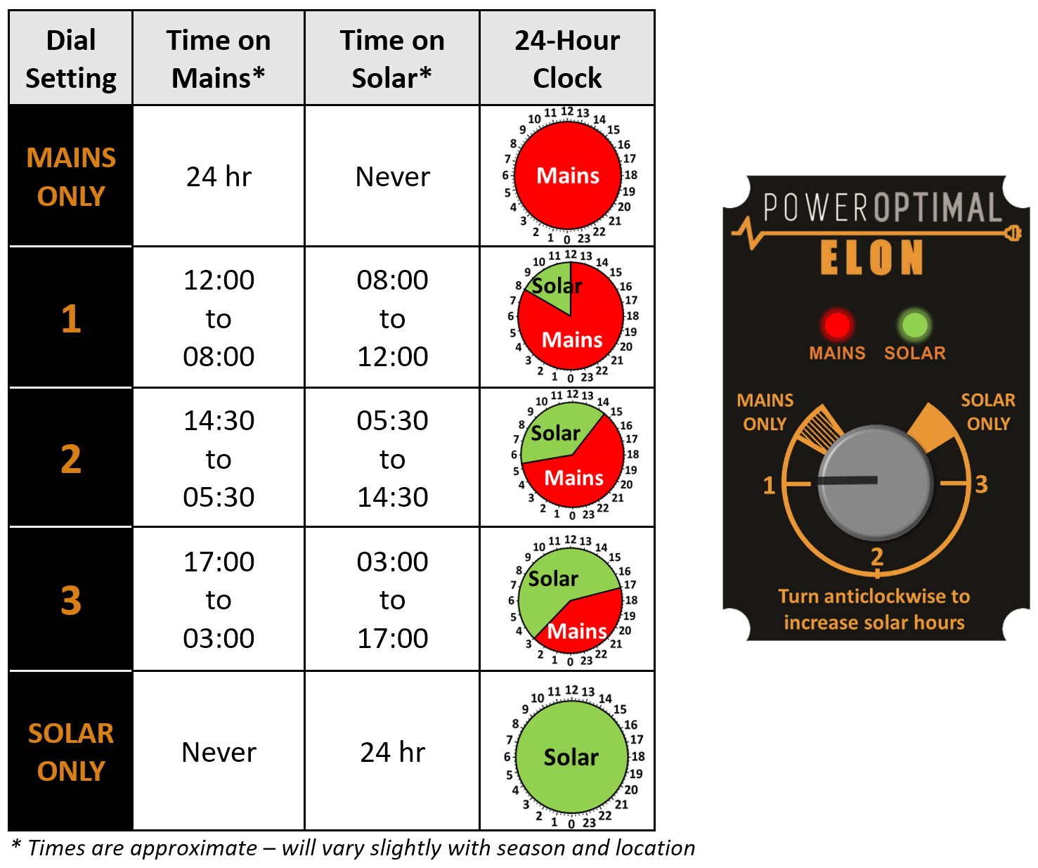
Think of the water in your geyser as a battery that can store energy in the form of hot water. To charge the battery (or heat the water) with solar energy during the day, it must cool down a bit in the morning. In other words, the water must be below its setpoint temperature by the time the sun comes up.
The Elon® achieves this by switching off mains power at some time in the morning, while you are still using hot water from the geyser. The table above indicates approximate switching times for different dial settings.
As you can see, as you turn the control dial from “MAINS ONLY” to “SOLAR ONLY”, the time period during which mains power is allowed to heat the water decreases to zero.
When the control dial is set to "MAINS ONLY", your geyser will use mains power 24 hours a day (in other words, it will never switch to solar power). The geyser will behave the same as any standard geyser.
Why would I ever want to set the control dial to “MAINS ONLY”?
Here are some example reasons why you might want to set the control dial to “MAINS ONLY”:
- You have a large number of guests, and you want to ensure hot water for everyone at all times;
- You want to do maintenance on the DC (solar) side, but still want hot water;
- There is a problem on the DC side (e.g. an insulation fault), but you still want hot water;
- You are going away for a long time and don't want the water in the geyser to be heated up whilst you are away. (Then you would set the switch to "MAINS ONLY" and switch off the geyser at the main house DB – see Section 2.4 Holiday Settings).
- Any other reason you might want to turn the geyser heating off completely.
If you only use hot water early morning and in the evenings, you can set it just outside the “SOLAR ONLY” zone (around the “3” mark) to benefit from a longer solar energy heating period (and save more money).
When the control dial is set to “SOLAR ONLY”, the Elon® 100 will ONLY use solar power to heat water.
If you set the control dial to “SOLAR ONLY”, you can increase the geyser thermostat temperature to 60 ºC to get maximum benefit from your solar array installation. We do not recommend setting the thermostat temperature above 60 °C. Remember to reduce the thermostat temperature again if you reduce the efficiency setting.

Warning: Do not set thermostat temperature above 65 ºC due to increased scalding risk. Be careful when opening hot water taps located close to your geyser. You can install a thermostatic mixing valve to reduce the risk of scalding – ask your plumber.
Please note: DO NOT install a separate timer on the AC side to try and regulate mains power use. Use only the Elon’s control dial to control mains power use. If you install a second timer, it will work at cross-purposes with the Elon and you will reduce performance and hot water availability.
Can I boost the water temperature with a single grid heating cycle whilst on “SOLAR ONLY” or any of the other settings?
The answer is YES. To boost water temperature to setpoint with a single grid heating cycle, turn the dial into “MAINS ONLY” until the red light starts flashing. Then turn the dial back to whatever previous setting it was on (or whatever setting you wish it to be on after the single grid heating cycle). The Elon will complete the single grid heating cycle (in other words, heat the water with grid power until it reaches the temperature set point) and then return to whatever setting you leave the control dial on.
2.4 Holiday settings
What setting should I use when I go on holiday?
You can either switch off both solar and mains power OR you can switch off mains power.
|
Setting |
How to set it |
Benefits & comments |
|
Mains power off |
Turn dial to SOLAR ONLY |
You will have hot water on your return, and it will cost you nothing. It will also prevent Legionella growth in your geyser. |
|
Both Mains & Solar power off |
Turn dial to MAINS ONLY and switch off geyser at distribution board |
Remember to switch system on when you return. |
2.5 How to maximise your savings
Control dial
The best way to maximise your savings is to set the Elon® control dial to “SOLAR ONLY”. This will ensure that the unit will never use grid (mains) power for heating water. You can still boost with mains power (for example on a cloudy day) by turning the dial to "MAINS ONLY" if needed.
However, the "SOLAR ONLY" setting will only be feasible if you have enough solar PV modules for your household (see the table in Section 1.3 above).
For most people, setting the dial at "3" will yield the most savings whilst maintaining hot water availability mornings and evenings.

Please note: The water in your geyser should be heated to 60 °C at least once a week to prevent Legionella bacterial growth[1]. If you have heavily overcast weather for more than a week on the SOLAR ONLY setting, turn the dial clockwise outside of the SOLAR ONLY zone for a day in order to supplement the solar water heating with grid electricity to reach the thermostat temperature setting.
When is the best time to shower?
If the control dial is set to “SOLAR ONLY”, it is best for people in the household to shower either in the morning or in the evening, but not both. (If you shower in the evening, cold water will mix with the remaining warm water overnight, and you will have cold water the next morning. If you do not shower again in the morning, the water will be heated during the day.)
If the control dial is set to any setting outside “SOLAR ONLY” or "MAINS ONLY", it is best to shower in the morning for maximum savings.
General hot water energy saving tips
- Shower, don’t bath
- Install water-saving / low flow shower heads (these also save energy because of reduced hot water use!)
- Reduce shower duration
- Check that your geyser is well insulated
South Africa is a water-scarce country – reducing hot water use saves both energy and water!
3. Maintenance
The Elon® 100 has been designed to last for a very long time and has no moving parts aside from three electrical relays. No maintenance is required on the Elon® 100.
3.1 Solar PV module maintenance
It is recommended that a qualified electrician inspect your solar PV installation at least once a year.
- At least once a week, check whether the indicator lights are flashing rapidly. (This indicates an isolation fault – call your electrician.)
- Perform regular visual checks (at least once a year). Check for soiling or any visible damage to any of the modules.
- If the modules have been soiled by dirt, dust, debris, bird droppings or any other materials, use water only and a sponge or soft cloth to clean them. Do the cleaning early in the morning or late in the afternoon, as the modules are hot during the day. Avoid using a water jet that may leave streaks on the modules.
- Visually inspect cables for any degradation or loose fittings.
- Look for any shading problems, such as trees that may have grown.
- An electrician can check solar power production on a sunny day to ensure that the system is still producing power at expected levels. A thermal imaging camera can be used to inspect modules for hot spots.
- Follow any specific maintenance instructions from the solar PV module manufacturer.
4. What to expect in terms of performance
4.1 Hot water production
Heating water takes a LOT of energy. A household geyser can use up to 40% of a house’s electricity. Heating a single 200 litre geyser from 15 °C to 60 °C will use over 10 kWh. This is about the same amount of energy burnt by a person running a distance of over 100 km at 10 km/hr, or enough energy to watch more than 120 hours of TV[2].
The more solar panels you have on your roof, the faster the Elon® 100 system will heat your water. Typically, the number of panels has been selected to heat water over most of the sunlight hours (from morning to afternoon). This will be slower than heating water using grid electricity. So you can expect a gradual temperature rise from morning to afternoon.

As one would expect, hot water production increases with increase in number of solar panels. Keep in mind that these numbers are averages over the year. This means that you should expect a lower number in winter and a higher number in summer.
4.2 Impact of location and seasons
The amount of energy from the sun depends on your location, the time of year as well as the orientation of your solar panels. The best direction for panels in South Africa is to face north, at an angle of about 25 to 35° from horizontal.

Although Gauteng (Johannesburg / Pretoria) & Cape Town may seem quite similar in terms of total solar energy per year, Cape Town has winter rainfall and Gauteng has summer rainfall. This leads to Cape Town having much lower solar electricity production than Gauteng in winter (see the below graph).

4.3 Payback period

As can be seen from the graph above, payback period decreases as number of solar panels increases, and is also different for Johannesburg, Cape Town and Durban[3].
The reason that payback period improves (decreases) as number of solar panels increases, is because there are some fixed costs (such as engineering design & safety components) and some costs that do not scale linearly with array size (such as labour, wiring, mounting kit costs, etc.).
5. Troubleshooting
5.1 Troubleshooting Guide for Users

Below you can find the same information with some further detail in table format. If you cannot resolve the problem using the diagram or table, please contact your installer.
|
Issue |
Possible causes |
What to do |
|---|---|---|
|
Water temperature too low |
|
|
|
Water temperature remains low after turning dial to "MAINS ONLY". (Note: the red LED light should start flashing once dial is turned to “MAINS ONLY”, indicating that the water is being heated.) |
|
|
|
Water temperature too high |
|
|
|
Hot water production is lower than it used to be |
|
|
|
Both indicator lights off |
|
|
|
Red or green indicator light flashing very fast |
|
|
5.2 Troubleshooting Guide for Electricians
NOTE: This Troubleshooting Guide is intended for electricians and not general users. Users should please refer to Section 5.1.
Things to Remember
- The red mains LED will only start functioning once stable mains voltage between 160 and 260 V AC is present for more than 4 minutes. (In other words, the Elon® will only allow mains power to the element 4 minutes after mains connection or switch-on.)
- Solar power is only recognised 40 seconds after active solar panels are connected to Elon®.
- An open thermostat (water at correct temperature) measures between 11 and 14 V DC across the “thermostat” terminals on the Elon®. Polarity across these terminals is not important.
- A closed thermostat (cold water) measures 0 V across the “thermostat” terminals on the Elon®.
- How to switch on solar power to element: With enough solar energy (check at solar terminals), solar power will be routed to the element within 15 seconds after the thermostat closes and the controller dial is set to “SOLAR ONLY”. A green flashing LED indicates this condition.
- How to switch on mains power to element: Turn control dial to “MAINS ONLY” and, if the thermostat is closed, mains power will be directed to the element indicated by a red flashing LED.
- Note: Once the dial has been turned to “MAINS ONLY”, it will complete a full mains heating cycle (until the thermostat opens). Turning the control back to “SOLAR ONLY” at this point will not immediately switch the unit back to solar power. It will only switch back again after the mains heating cycle is completed (i.e. the thermostat opens) and the thermostat then closes again. You can finish the mains heating cycle faster by reducing the thermostat temperature setting until the thermostat opens. Test solar power first.
- Fast flashing red / green LEDs indicate a short between a PV (photovoltaic) lead and earth OR a partial short of the element to earth. Wait at least 20 seconds after any disconnection or other correction step for the LEDs to stop flashing.
- If you are having DC power supply issues, check if the DC circuit breaker or isolator is faulty by measuring the voltage across the DC circuit breaker or isolator whilst DC power is being supplied to the element. If there is a voltage drop across the disconnect switch, it is faulty and needs to be replaced. Also check all DC fuses if installed.
Troubleshooting Steps
- 🞏 Confirm correct wiring and polarity to Elon®. Also confirm test meter wires are connected correctly, black to common!
- 🞏 Confirm correct voltages and currents of all connections through the following steps:
- Confirm open / closed thermostat voltages (11 – 14 V DC open, 0 V DC closed).
- Confirm controller wire is connected properly. The connections should “click” into place and appropriate LEDs should indicate (be active).
- With solar power to element switched on (green LED flashing), confirm same DC voltage to element as measured at solar terminals.
- With DC clamp meter confirm that there is an active current through element.
- With mains power to element switched on (red LED flashing), confirm same AC voltage to element as measured at mains terminals (should be approx. 230V AC).
- With AC clamp meter confirm active current through element of between 9 and 18 Amps depending on element rating.
- 🞏 If you used a test controller for troubleshooting, remember to plug the wire from the installed controller back into the Elon® and check functioning. Set thermostat back to original setting.
Appendix A. IEC/SANS and EMC Test Certificates: Elon® 100


Appendix B. Warranty
If the PowerOptimal Elon® 100 (“the Product”) is found to be defective, you will be entitled to a repair or replacement within 2 (two) years of the date of delivery of the Product to you. Please keep your receipt as proof of purchase. If you are a consumer as defined in the Consumer Protection Act No. 68 of 2008 (“the CPA”), you will be entitled to such remedies as are made available under the CPA in relation to the return of goods.
PowerOptimal will not have any liability or obligation to you where the Product has been subjected to abuse, misuse, improper use, improper testing, negligence, accident, alteration, tampering or repair by a third party.
To the maximum extent permitted by applicable law, in no event shall PowerOptimal be liable for any special, incidental, indirect, or consequential damages whatsoever, including, without limitation, damages for loss of business profits or business interruption, arising out of the use or inability to use this product.
Please note that this unit must be installed by an electrical contractor registered with the Department of Labour. Failure to do so may invalidate this warranty. Please keep the CoC (Certificate of Compliance) issued by the electrical contractor on completion of the installation.
Appendix C. Terminology
AC Alternating Current – an electric current that reverses its direction many times a second at regular intervals, with voltage typically varying in the form of a sine wave.
CoC Certificate of Compliance – to be issued by the electrician installing your Elon® 100 system
CPA Consumer Protection Act No. 68 of 2008
DB Distribution board – the main electrical distribution board / panel in your home, containing circuit breakers and switches.
DC Direct Current – an electric current flowing in one direction only. Solar PV modules produce direct current electricity.
Geyser South African term for a water heater
IEC International Electrotechnical Commission
kWh A derived unit of energy equal to 3.6 MJ (megajoules). The amount of energy used by a 1 kW electrical device over a period of 1 hour.
kWp or Wp The peak power rating in kilowatt (kW) or watt (W) of a solar module or array – i.e. the output power achieved under full solar radiation. This is usually reported at STC and NOCT.
PV Photovoltaic – referring to the production of electric current at the junction of two materials exposed to light.
SANS South African National Standards
Notes
-
See for example: http://www.eskom.co.za/sites/idm/Documents/Legionaires_Fact_sheet_hot_water_bacteria_simple_facts.pdf and http://standards.nsf.org/apps/group_public/download.php/30413/How%20to%20Avoid%20LD%20at%20Home.pdf ↑
-
46” OLED TV at 82W. ↑
-
Calculations based on actual Elon performance, assuming a 20% reduction due to non-optimal user behaviour, an initial electricity tariff of R3/kWh and an annual electricity price increase of 8%. ↑
PowerOptimal Elon® 100 Installation Manual v2.30

Version date: 2025/12/28
Enquiries: info@poweroptimal.com
Address: Postnet Suite 21, Private Bag X21, Tyger Valley, 7536
Patented: ZA2019/02129

SAFETY WARNING
- Installation of the Elon® 100 should ONLY be performed by an electrical contractor registered with the Department of Labour (the so-called “wireman’s licence”) and strictly according to the installation instructions in this manual. The electrician should provide you with a supplementary Certificate of Compliance (CoC) once installation is completed.
- We strongly recommend that you use a reputable and experienced solar photovoltaic (PV) system installer to install your solar PV modules.
- Solar PV modules exposed to the sun are live (i.e. will produce electricity) and can give an electric shock. Special care should be taken and only trained solar PV installers should install the modules.
- Do not attempt to alter or service the electrical installation, or open the Elon® 100 unit or controller for any purpose.
- Use the Elon® 100 only for its intended purpose.
- Always make sure that every wiring connection is properly tightened.
- Do not earth either of the solar module wires (but do earth the frames).
- All installation wiring should be at least 2.5mm².
- Avoid coiling, since DC switching can create damaging spikes.
- Keep all wires as short as possible.
Refer to the PowerOptimal website for the following:
|
|
|
|
|
|
|
|
|
|
|
|
 Online Elon® Basic Training Course
Table of Contents
Table of Contents
1. Required tools
2. Basic wiring diagram
3. Solar PV array installation
4. Elon® 100 installation
5. Element installation (retrofit)
Appendix A. Basic Troubleshooting Guide for Electricians
Appendix B. Solar yield
B1. Solar irradiance levels
B2. Geographic features
B3. Azimuth / horizontal angle
B4. Inclination or tilt angle
B5. Shading
B6. Ambient temperature
B7. Minimum distance from roof edges
Appendix C. Deciding on Size of Solar Array
Appendix D. PV array and geyser (water heater) element matching
Appendix E. Technical Specification Summary: Elon® 100
Appendix F. Surge Protection Device (SPD) Recommendations
F1. SANS 10142-1 The wiring of premises Part 1: Low-voltage installations
F2. Draft standard SANS 10142-3 Proposed Interim Guideline for the wiring of LV grid-embedded PV installations not exceeding 1000kVA in South Africa
Appendix G. IEC/SANS and EMC Test Certificates: Elon® 100
Appendix H. Warranty
Appendix I. Terminology
Notes
1. Required tools
The following tools are required for the installation. Use insulated tools wherever applicable.
- Solar modules (mounting) - please refer to solar module / mounting installation instructions – the below is only a guideline:
- Cordless screwdriver with bits
- Drill
- Set of drill bits (wood, steel, stone)
- Set of screwdrivers
- Set of Allen (hex) keys
- Tape measure
- Grinder (tile roof installations)
- Permanent marker
- Chalk
- Hammer
- Solar modules (electrical):
- AC/DC Clamp meter
- Side-cutting pliers
- Screwdriver set
- Crimping tool
- 4 mm² wire (double insulated) (or other size as determined by solar PV voltage and wire length)
- Cable ties
- Elon® 100 - the following additional tools:
- 2.5 mm² panel wire
2. Basic wiring diagram

Note 1: Both AC & DC circuit breakers or isolators must be installed within 1.5m of the geyser (water heater), line of sight.
Note 2: Surge Protection Device (SPD) only required in higher lightning strike density areas (such as parts of Gauteng and Mpumalanga), or where the DC cables are long. See Appendix F.

Wiring detail: Elon 100 with wiring kit
Wiring kit for Elon 100:

Wiring diagram for Elon 100 with wiring kit:

Note: Surge Protection Device (SPD) only required in higher lightning strike density areas (such as parts of Gauteng and Mpumalanga), or where the DC cables are long. See Appendix F.
Wiring detail: Elon 100 with element adapter
Element adapter side view and front view:


Wiring diagram: Elon 100 with element adapter:

Note: Surge Protection Device (SPD) only required in higher lightning strike density areas (such as parts of Gauteng and Mpumalanga), or where the DC cables are long. See Appendix F.
3. Solar PV array installation
Modules should ONLY be installed by a trained solar PV installation technician. Array position and orientation have a major impact on power production (see Appendix B).
Review the instructions from your solar PV module supplier / manufacturer on installation.

Please note: Your installer should comply with SANS 10142-1 (Standard for low voltage installations) and SANS 60364-7-712 when doing your solar PV installation. If they are not well familiar with these standards, you should look for a different solar PV installer.
SAPVIA (South African Photovoltaic Industry Association) has made available an excellent guide to solar PV installations. See:
https://www.pvgreencard.co.za/Solar%20PV%20Guidelines%20-%20Digital%20Spread%20High-res.pdf
NB: Refer to Appendices C & D for guidelines on selecting the right size solar PV array for the user requirements, and for correctly matching the solar PV array and the geyser element.
The below installation steps are a general guide only – compliance with the abovementioned standards is compulsory.
- A critical starting point is safety gear: ensure that all installers wear a helmet and insulated safety gloves, as well as fall protection safety gear if work will be done on a roof or elevated area.
- The solar PV array should only consist of one string of 2 to 6 modules in series, or two parallel strings 2 to 5 modules each. Do not exceed the DC voltage or current ratings of the Elon® 100 (240V DC and 20A DC) under any circumstances. Do not exceed the maximum power rating of 4 kWp.
- Attach bracket / mounting structure to roof. Use mounting structure recommended by solar module supplier for roof type and size of solar modules.
- Fix the solar PV modules to the mounting structure whilst connecting the module cables to each other.
- If practical, cover the modules to ensure that there is no potential for electric shock whilst installing the system.
- Ground the mounting structure only.
- Install the wiring from the solar PV array to the Elon® 100 unit in the ceiling space. Ensure circuit breakers / isolators are in the “Open” position. Installation of a Surge Protective Device (SPD) between the solar PV array and the Elon® 100 is required in high lightning strike areas, such as parts of Gauteng and Mpumalanga. See Appendix F for more information.
- Last step is to connect the array to the rest of the wiring, making sure that both the positive and negative wires are fully isolated from ground and keeping circuit breakers / isolators in the “Open” position.
Some “DO’s & DON’T’s” when installing solar PV arrays:
Your solar PV installer should not make any of these basic mistakes, but they are listed here just in case.
- DO earth the PV array structure.
- DO isolate the wires from the PV array structure.
- DON’T use different sizes, types or specifications of modules together in the same string or array.
- DON’T install solar arrays where they will be partially shaded during any season of the year if it can be avoided at all.
- DO install the arrays so that there is space for inspection or maintenance when needed.
- DO use cabling of the correct size for your solar array.
- DON’T install the solar array flush with your rooftop. Use struts / brackets that ensure an unrestricted air gap of at least 40 mm between the roof and the modules.
- DON’T walk on the modules.
- DO ensure that connectors are kept clean and away from water.
- DON’T leave exposed modules in short circuit.
- DO ensure that all connectors are securely fastened.
- DON’T exceed the voltage ratings of any components.
- DO properly route and secure all cables.
- DON’T coil cables.
4. Elon® 100 installation
A note on poor geyser installations
Poor geyser installations can cause excessive heat loss, which increases electricity cost with no benefit. Check for the following:
- There should be lagging (insulation) installed on at least the first meter of the hot water outlet pipe and the cold water inlet pipe.
- If the hot water outlet pipe is routed upwards from the geyser, a U-bend heat trap has to be installed, otherwise natural hot water convection (circulation) will cause excessive heat loss from the geyser
- The geyser itself should have good quality insulation. (All new geysers since 2013 have had to comply with more stringent insulation requirements and should have good quality insulation.)
- If there is a solar thermal system still connected to the geyser, it is strongly recommended to uninstall it, or at the very least ensure that there are closed shut-off valves on both entering and exiting pipes.
- If there is a hot water circulation system installed in the house, good insulation along the whole pipe length is critical. Circulation times should also be kept to a minimum.
- It is NOT recommended to use a geyser timer together with the Elon 100 system.
- Isolate the geyser – switch off the geyser circuit breaker at the main electrical distribution board (DB) AND switch off the geyser isolator at the geyser.
- Confirm with a multimeter that there is no voltage across the wires.
- Install circuit breaker (or isolator and fuse) for solar PV (DC) supply. Also install AC supply isolator / circuit breaker if there is none. NB Ensure that the DC circuit breaker is rated for the DC voltage and current of the installed solar PV array.
- The circuit breakers / isolators must be installed within 1.5m of the geyser AND must be line of sight / visible (i.e. do not install them at the back of the geyser).
- The DC wires must not be earthed – i.e. they must be fully isolated from earth. Do NOT test with a Megger.
- Keep the DC wires as short as possible.
- Avoid any coils in DC wires.
- Recommended wiring size is at least 2.5 mm². Use panel wire for all connections to the Elon® 100.
- Install the Elon® 100 unit according to wiring diagram (see Section 2).
- Mount the Elon® 100 unit close to the geyser and protect from outside elements. The maximum wire length between Elon® 100 and geyser is 3 m.
- It is recommended to install the Elon® 100 oriented with wiring exiting downward to minimise the risk of water ingress. The enclosure is IP65, but the glands and wires represent a potential water ingress point if not installed correctly.
- Mount the controller (the small black remote control) inside or next to the main DB in the house or in another convenient and accessible location (for example the garage). Double-sided mounting tape and Genkem contact adhesive work well for most surfaces. When inserting the controller wire into the Elon® 100 unit, make sure the connector clicks into place.
Note: if installing the controller outside or in a humid or corrosive area (such as by the coast), install the controller in a weatherproof box, such as a weather proof plug box. Apply silicon at the bottom (cable entry point).
10. Connect the Elon® 100 and thermostat last.
You will have been provided with either a wiring kit (FOLLOW INSTRUCTIONS 10A) OR an element adapter (FOLLOW INSTRUCTIONS 10B). See also the training videos on how to install either of these here: https://www.poweroptimal.com/elon-100-training/.
10A WIRING KIT INSTRUCTIONS (follow these if you have the wiring kit as per Section 2)
Note: As per the wiring diagram, the thermostat and element should be connected to the Elon® SEPARATELY (independently).


10A-1 For TSE and Thermowatt (RTS) thermostats, connect the connectors marked “thermostat” on the Elon® directly to the two screw terminals on the thermostat and short the two male terminals at the bottom of the thermostat together, using the bridging wire with female connectors supplied with the Elon® 100 (see the photos above). (Less than 20 mA DC current will flow through this wire – it is a sensing current only.) There must be no connection between the thermostat and the element.


10A-2 Connect the two element terminals directly to the connectors marked “element” on the Elon®. For flange-type elements, use the supplied wiring with element connector (photos above). Make sure that the element connector fits tightly into the element and that the two male spade terminals of the connector are slotted correctly into the female terminals of the element. Crimp both terminals (you can do this through the plastic cover) to ensure a tight fit on both sides.
10A-3 Slide the thermostat (with bridging wire installed) into the thermostat pocket in the element as deep as it can go. (Slide it in rotated 180 ° from its normal orientation.)
10A-4 Continue with instructions from STEP 11.
10B ELEMENT ADAPTER INSTRUCTIONS (follow these if you have the element adapter as per Section 2)


10B-1 Plug the thermostat into the element adapter as per photo above, ensuring a snug fit. Check that spade terminals enter female terminals correctly.
10B-2 Plug the thermostat + element adapter into the element as per Figure 4.8, ensuring a snug fit. Tug on each side to confirm correct fit.
10B-3 Wire the thermostat screw terminals directly to the connectors marked “Thermostat” on the Elon.
10B-4 Wire the element adapter directly to the connectors marked “Element” on the Elon.
10B-5 Continue with instructions from STEP 10.
11. Set the thermostat to the desired temperature (60 °C maximum). Note that vertically installed geysers have higher temperatures at the top than the bottom (this is called thermal stratification). The temperature difference is about 3 °C per meter. Reduce the setpoint temperature in vertically installed geysers to about 5 °C lower than for a horizontally installed geyser.
12. Attach labels included with the Elon 100 (see Figure 4.9 on next page):
-
- Attach "Dual Supply" labels to the AC isolator and the DC circuit breaker (or isolator).
- Attach "Warning – Photovoltaic Power Source" label to the DC wiring conduit in a clearly visible position.
- Attach "Installation Diagram" label close by the geyser in a clearly visible position – for example on a rafter. (Do not attach it directly to the geyser, as it will disappear if the geyser is replaced.)
13. Once installation is complete, do the following:
-
- Turn the control dial to "SOLAR ONLY".
- Switch on the AC & DC circuit breakers or isolators.
- Remove the covering from the solar modules.
- Switch on the geyser circuit breaker at the main DB.

Label positions (see step 12)
14. Check that the Elon® 100 unit is operational (refer to LED lights on controller – see next page).
-
- Confirm solar PV array supply voltage and DC power to geyser when thermostat is closed. The Elon® 100 will switch DC power to the geyser approximately 10 to 15 seconds after DC power to the Elon® has been switched on (if there is enough sunlight). (If thermostat is not closed, open hot water tap in house until thermostat closes.)
- Test mains power supply by turning the dial to "MAINS ONLY". The red light should start flashing (except if geyser is already at thermostat setpoint temperature). NOTE THAT THE ELON® WILL ONLY SWITCH TO MAINS 5 MINUTES AFTER MAINS POWER SWITCH-ON OR RECONNECTION. This is to allow grid power to stabilize after a power failure.
- Confirm that no power is supplied to geyser element when thermostat is open (turn thermostat set point to lowest setting).
- Set thermostat back at desired temperature (60 °C maximum).
15. Set control dial to setting “2” (the 6 o' clock position). (For new property development installations, you can set the control dial to setting “1” (the 9 o’clock position). This ensures that new residents can settle in before deciding on the setting that suits their habits best.)
Note: if doing any maintenance, rewiring or disconnecting the Elon® 100 or geyser element for any reason, it is good practice to first switch off both the AC & DC circuit breakers / isolators, and then disconnect one of the wires between the Elon® 100 and thermostat before disconnecting the rest of the wires.
Please note: DO NOT install a separate timer on the AC side to try and regulate mains power use. Use only the Elon’s control dial to control mains power use. If you install a second timer, it will work at cross-purposes with the Elon and you will reduce performance and hot water availability.
Final step: hand over the laminated Quick Reference User Guide (included in the box) to the household (or leave it in a prominent place for them to find such as the kitchen counter).
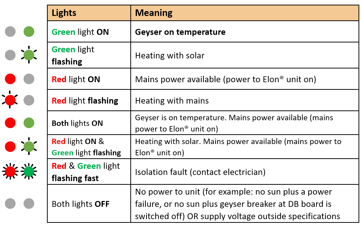
The Mains & Solar indicator lights indicate the following conditions:
The control dial sets the mains & solar times as follows:
5. Element installation (retrofit)
If you need to exchange the element on an existing geyser, please follow the instructions provided by the element supplier.
There are two main types of geyser heating elements: screw-in and flange type. There are three main types of thermostats: VKF-11, TSE and Thermowatt (the TSE and Thermowatt thermostats are quite similar). The below table provides a guide to Elon® compatibility with the different elements and thermostats.
|
Element type |
Compatible thermostat type |
Comments |
|---|---|---|
|
Screw-in element:
|
VKF-11 thermostat: |
Element & thermostat have separate electrical connections, so each can be connected (wired) separately to the Elon®. Thus, this element-thermostat combination is directly compatible with the Elon®. (No need to use the bridging wire or element adapter supplied with the Elon® unit.) The thermostat pocket in the element is the right size for the VKF-11 thermostat. Do not connect the thermostat in line with the element. Connect the two thermostat wires to the two terminals marked “thermostat” on the Elon 100 unit. Connect the element separately to the two terminals marked “element” on the Elon 100 unit. |
|
Spiral element (flange type) with smaller diameter thermostat pocket:    |
TSE thermostat: Thermowatt (RTS) thermostat:  |
The spiral element generally has a smaller thermostat pocket than the screw-in element. The TSE and Thermowatt (RTS) thermostats fit into this smaller pocket. The VKF-11 thermostat requires a larger pocket and does not fit into standard spiral element pockets. The TSE and Thermowatt thermostats normally clip directly into the element, but this won’t be the case when the Elon® is connected. Use the wiring kit or element adapter supplied with the Elon® (see Figures 4.1 and 4.2 above) to connect the Elon® to these thermostats and elements. |


Appendix A. Basic Troubleshooting Guide for Electricians
NOTE: This Troubleshooting Guide is intended for electricians and not general users. Users should please refer to the User Manual, which can be found at www.poweroptimal.com/manuals.
Things to Remember
- The red mains LED will only start functioning once stable mains voltage between 190 and 260 V AC is present for more than 5 minutes. (In other words, the Elon® will only allow mains power to the element 5 minutes after mains connection or switch-on.)
- Solar power is only recognised 40 seconds after active solar panels are connected to Elon®.
- An open thermostat (water at correct temperature) measures between 11 and 14 V DC across the “thermostat” terminals on the Elon®. Polarity across these terminals is not important.
- A closed thermostat (cold water) measures 0 V across the “thermostat” terminals on the Elon®.
- How to switch on solar power to element: With enough solar energy (check at solar terminals), solar power will be routed to the element within 15 seconds after the thermostat closes and the controller dial is set to “SOLAR ONLY”. A green flashing LED indicates this condition.
- How to switch on mains power to element: Turn control dial to “MAINS ONLY” and, if the thermostat is closed, mains power will be directed to the element indicated by a red flashing LED.
- Note: Once the dial has been turned to “MAINS ONLY”, it will complete a full mains heating cycle (until the thermostat opens). Turning the control back to “SOLAR ONLY” at this point will not immediately switch the unit back to solar power. It will only switch back again after the mains heating cycle is completed (i.e. the thermostat opens) and the thermostat then closes again. You can finish the mains heating cycle faster by reducing the thermostat temperature setting until the thermostat opens. Test solar power first.
- Fast flashing red / green LEDs indicate a short between a PV (photovoltaic) lead and earth OR a partial short of the element to earth. Wait at least 20 seconds after any disconnection or other correction step for the LEDs to stop flashing.
- If you are having DC power supply issues, check if the DC circuit breaker or isolator is faulty by measuring the voltage across the DC circuit breaker or isolator whilst DC power is being supplied to the element. If there is a voltage drop across the disconnect switch, it is faulty and needs to be replaced. Also check all DC fuses if installed.
Troubleshooting Steps
- 🞏 Confirm correct wiring and polarity to Elon®. Also confirm test meter wires are connected correctly, black to common!
- 🞏 Confirm correct voltages and currents of all connections through the following steps:
- Confirm open / closed thermostat voltages (11 – 14 V DC open, 0 V DC closed).
- Confirm controller wire is connected properly. The connections should “click” into place and appropriate LEDs should indicate (be active).
- With solar power to element switched on (green LED flashing), confirm same DC voltage to element as measured at solar terminals.
- With DC clamp meter confirm that there is an active current through element.
- With mains power to element switched on (red LED flashing), confirm same AC voltage to element as measured at mains terminals (should be approx. 230V AC).
- With AC clamp meter confirm active current through element of between 9 and 18 Amps depending on element rating.
- 🞏 If you used a test controller for troubleshooting, remember to plug the wire from the installed controller back into the Elon® and check functioning. Set thermostat back to original setting.
Appendix B. Solar yield
Note: only basic information is provided here. Your solar PV installation design engineer or technician should advise on the best configuration for your specific location, roof structure, etc.
The yield produced by solar PV modules depends on several factors:
- Solar irradiance levels at your location (which varies with time of day, season and weather conditions)
- Geographic features at your location (e.g. mountains or buildings causing morning or afternoon shade)
- Azimuth and tilt of the modules
- Shading
- Ambient temperature (also influenced by wind)
B1. Solar irradiance levels
 The map below shows the general solar irradiance levels (GHI or Global Horizontal Irradiance) in South Africa[1]:
You can expect the following approximate energy generation from solar modules for various locations[2]:
|
Location |
Electricity generated kWh/kWp per year |
|
Bloemfontein |
2055 |
|
Cape Town |
1762 |
|
Durban |
1570 |
|
Johannesburg / Pretoria |
1871 |
|
Mbombela |
1766 |
|
Gqeberha / Port Elizabeth |
1698 |
|
Upington |
2075 |
B2. Geographic features
Major geographical features (such as hills or mountains) can reduce the total solar yield.
B3. Azimuth / horizontal angle

The azimuth refers to the horizontal orientation of the modules – in the Southern Hemisphere, by how many degrees they are oriented away from north
Due north is best in the Southern hemisphere. Modules should preferably not be oriented more than 15º away from due north.
B4. Inclination or tilt angle
The tilt angle refers to the vertical orientation of the modules – a rough guide is that the modules should be tilted at the site’s latitude. For example, Musina is 22º S, Pretoria & Johannesburg are 26º S, Bloemfontein is 29º S, Durban is 30º S and Cape Town & Port Elizabeth are 34º S.
To optimise winter performance, one can add 15º to the tilt angle. (Note: as long as you are within about 15º of the optimal latitude, the loss in efficiency is not substantial.)
B5. Shading
Solar modules lose a lot of efficiency if even a small part of the module is shaded. For example, just 3% shading can cause a 25% loss in power! Shaded cells on a module also causes hotspots, which will reduce module lifetime.
It is thus important to place the solar modules on a rooftop area that is free from shading for as much as possible of the day (and throughout the year).
B6. Ambient temperature
Solar PV modules’ performance decreases with increasing temperature. Wind will reduce the temperature of the solar array and will thus improve performance. Thus, it is important to install rooftop solar modules with an air gap of at least 40 mm between the modules and roof[3].
B7. Minimum distance from roof edges
Your solar PV design engineer should prescribe minimum clearance from roof edges that should be maintained for your area based on climatic and wind conditions. Typically, a minimum clearance of 20 to 30 cm should be maintained.
Appendix C. Deciding on Size of Solar Array
Terminology used

Solar power is generated by solar cells, which are arranged in framed modules, typically of 60 or 72 cells each. The total set of solar PV modules installed is referred to as a solar PV array[4].
The table below provides a basic guide to selecting the size of the solar PV array based on number of people in the household and/or hot water use. Minimum recommended size is 1 kWp. Read on for a more detailed guide.
TABLE C1. ANNUAL AVERAGE LITRES OF WATER HEATED PER DAY
The below example table indicates the average number of litres of water per day that the system will heat from 15 to 60 °C over a year period for different solar array peak power ratings. (The amount of water heated will vary with weather conditions, by geographic location and by season. Water heated per day will be significantly lower in winter and significantly higher in summer. These numbers indicate heating capacity – i.e. if no hot water is used on a given day, there will be less water heated on that day. This is only an approximate guide.)
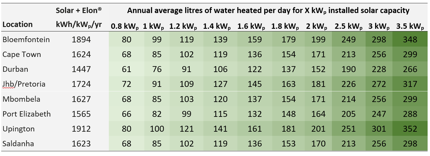
Example:
For a solar array of 1.2 kWp, an installation in Johannesburg would yield about 1724 kWh/kWp/yr, or 1724 x 1.2 kWp = 2069 kWh/yr. This would be sufficient to heat on average 109 litres of water per day. For a family of 2 each using 80 litres of hot water per day, this would provide about 109 ÷ (80 x 2) or 68% of the annual hot water requirement.
TABLE C2. ANNUAL AVERAGE NUMBER OF SHOWERS PER DAY
The below table indicates the average number of showers per day for which the system will supply hot water over a year period for different solar array peak power ratings. (The amount of water heated will vary with weather conditions, by geographic location and by season. Water heated per day will be significantly lower in winter and significantly higher in summer. These numbers indicate heating capacity – i.e. if no hot water is used on a given day, there will be less water heated on that day. This is only an approximate guide.)
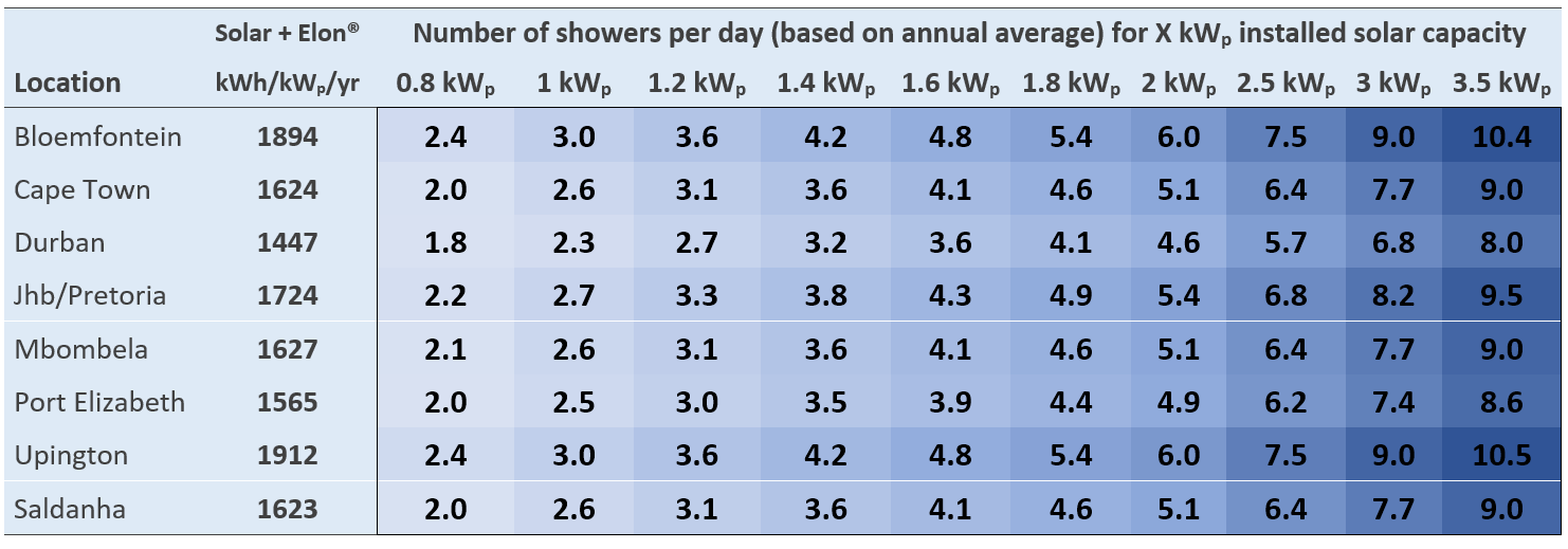
The table is based on 6-minute showers at 40 °C and 8 litres/min low flow showerheads. Old showerheads can use up to 15 litres/min and would substantially reduce the number of showers.
Example:
For a solar PV array of 2.5 kWp, an installation in Johannesburg would yield about 1724 kWh/kWp/yr, or 1724 x 2.5 kWp = 4 310 kWh/yr. This would be sufficient for about 6 to 7 showers per day.
TABLE C3. PERCENTAGE OF ANNUAL HOT WATER REQUIREMENT
The below example table indicates what % of the annual hot water requirement will on average be supplied by the system for 2 people each using 80 litres of hot (60 °C) water per day. (The amount of water heated will vary with weather conditions, by geographic location and by season. Water heated per day will be significantly lower in winter and significantly higher in summer. These numbers indicate heating capacity – i.e. if no hot water is used on a given day, there will be less water heated on that day. This is only an approximate guide.)
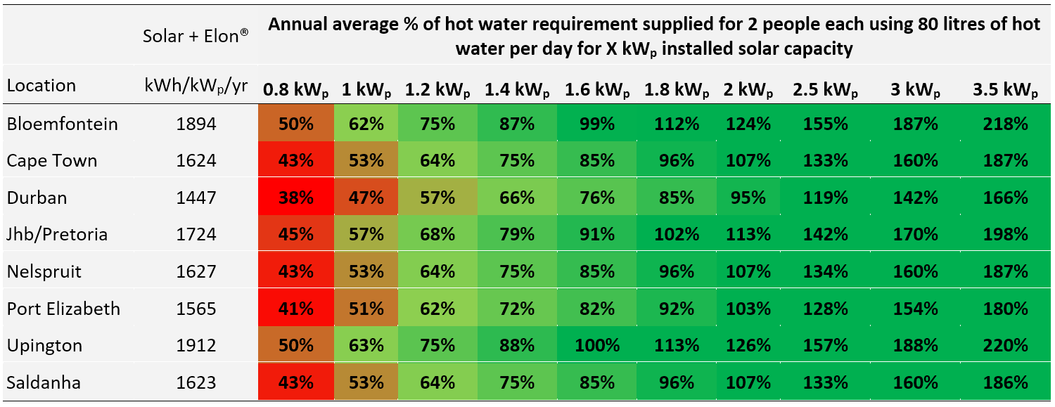
Examples:
An array of 1.2 kWp will provide approximately 64% of the annual hot water requirement for a family of two people in Cape Town.
An array of 2 kWp will provide approximately 124% x (2 people / 4 people) = 62% of the annual hot water requirement for a family of four people in Bloemfontein.
Appendix D. PV array and geyser (water heater) element matching
It is important to match PV array specifications and heating elements for maximum power transfer efficiency. See the below table for the recommended heating element power rating for different solar array sizes.
Contact PowerOptimal for advice on module-element matching if module properties are significantly different to typical values or for advice on bifacial, high current & high voltage modules.
TABLE D1. GUIDE: PV ARRAY AND GEYSER (WATER HEATER) ELEMENT MATCHING
DO NOT DEVIATE FROM THE RECOMMENDED MODULE-ELEMENT MATCHING CONFIGURATIONS WITHOUT CONSULTING POWEROPTIMAL.
Maximum allowed solar PV array specifications at Standard Test Conditions (STC):
Isc < 20A Voc < 250V Power < 4 kWp
Appendix E. Technical Specification Summary: Elon® 100
Refer to the PowerOptimal website for the full Technical Specification www.poweroptimal.com/specifications
|
Rated input voltage |
250V AC, 250V DC |
|
Rated input current |
25A AC, 20A DC |
|
Mains (AC) voltage range |
-50% to +100% (but will disconnect all loads when breach is greater than +/- 15%) |
|
System power supply |
Solar or 230V AC mains |
|
Power consumption |
<3W on mains power; <0.5W on solar power |
|
Shutdown |
Sufficient power supply capacity to manage processor, switching and data storage if both mains and solar supply fail |
|
Solar voltage (Voc at STC) |
20 – 250 V DC |
|
Solar energy availability |
Automatically determines availability of sufficient solar energy before supplying load from solar modules |
|
Controller settings |
Can be adjusted to run from “solar only” (100% solar energy use) to "mains only" (no solar energy use) |
|
Thermostat |
Uses the standard normally open thermostat switch associated with the geyser element as a sensor only, with less than 10mA sense current, to control power to the element |
|
Reverse polarity protection |
Protected against reverse connection of solar array |
|
Enclosure ingress protection rating |
Elon 100 main unit: IP65 Elon 100 remote control: IP40 (install indoors or in waterproof enclosure) |
|
Maximum distance Elon® unit to controller |
10 m |
|
Annual energy production compared to inverter-based system |
> 90% when solar array and geyser element are matched correctly |
|
Standards conformance |
IEC / SANS 60669-1, 60669-2-1, 60730-1, 60335-1, 60335-2-21, CISPR 11 & IEC 61000-6-1 |
|
Dimensions & weight |
Elon® 100 main unit: 200 x 150 x 60 mm (LxWxH), 1.75 kg. Controller: 50 x 72 x 41 mm (LxWxH) |
|
Patents |
ZA 2019/02129 |
It is important to match modules and heating elements for maximum power transfer efficiency. See the tables in Appendix D for the recommended heating element power rating for different solar module specifications and array configurations.
Appendix F. Surge Protection Device (SPD) Recommendations
This Appendix outlines under which circumstances a Surge Protection Device should be installed as part of a solar PV system installation such as the Elon® 100.
F1. SANS 10142-1 The wiring of premises Part 1: Low-voltage installations
Please note: compliance with SANS 10142-1 is compulsory for all electrical installations as per the Occupational Health & Safety Act.
SANS 10142-1 states the following with regards to surge protection:
6.7.6 Surge protection
6.7.6.1 Surge protective devices (SPDs) may be installed to protect an installation against transient overvoltages and surge currents such as those due to switching operations or those induced by atmospheric discharges (lightning). NOTE A risk assessment may be performed in accordance with annex Q. The Installation of SPDs is necessary where structures are equipped with external lightning protection systems (LPS) as in accordance with SANS 10313.
As can be seen above, surge protection is optional and based on a risk assessment as per Annex Q.
The risk assessment is as per the following table from SANS 10142-1 (2020):

Note that the “Service Line” referred to above is the incoming (AC) line for the house.
Here is a lightning density map for South Africa as provided in SANS 10142-1:

F2. Draft standard SANS 10142-3 Proposed Interim Guideline for the wiring of LV grid-embedded PV installations not exceeding 1000kVA in South Africa
Please note: this is only a draft standard and compliance with this standard is not compulsory. It is only provided for information purposes.
The draft standard SANS 10142-3 requires a Surge Protection Device to be installed where the length (L) of the DC cables (from PV array to Elon® 100 or inverter) exceeds the critical length Lcrit as follows:
A Surge Protection Device is required where L ≥ Lcrit
The critical length Lcrit depends on the type of PV installation and is calculated according to the following table:
|
Type of installation |
Individual residential premises |
Terrestrial production plant |
Service / Industrial / Agricultural Buildings |
|
Lcrit (in meter) |
115/Ng |
200/Ng |
450/Ng |
where Ng = lightning strike density (number of strikes/km²/yr)
The length of DC cables L is the sum of:
- distances between the inverter(s) and the junction box(es), while observing that the lengths of cable located in the same conduit are counted only once, and
- distances between the junction box and the connection points of the photovoltaic modules forming the string, observing that the lengths of cable located in the same conduit are counted only once.
For the Elon® 100, distance L is the length of DC cables from PV array to the Elon® 100.
Here is a national lightning ground stroke density map for South Africa[5].

From Evert & Gijben (2017).
From this map, the lightning strike density (Ng) range for major cities are as follows:
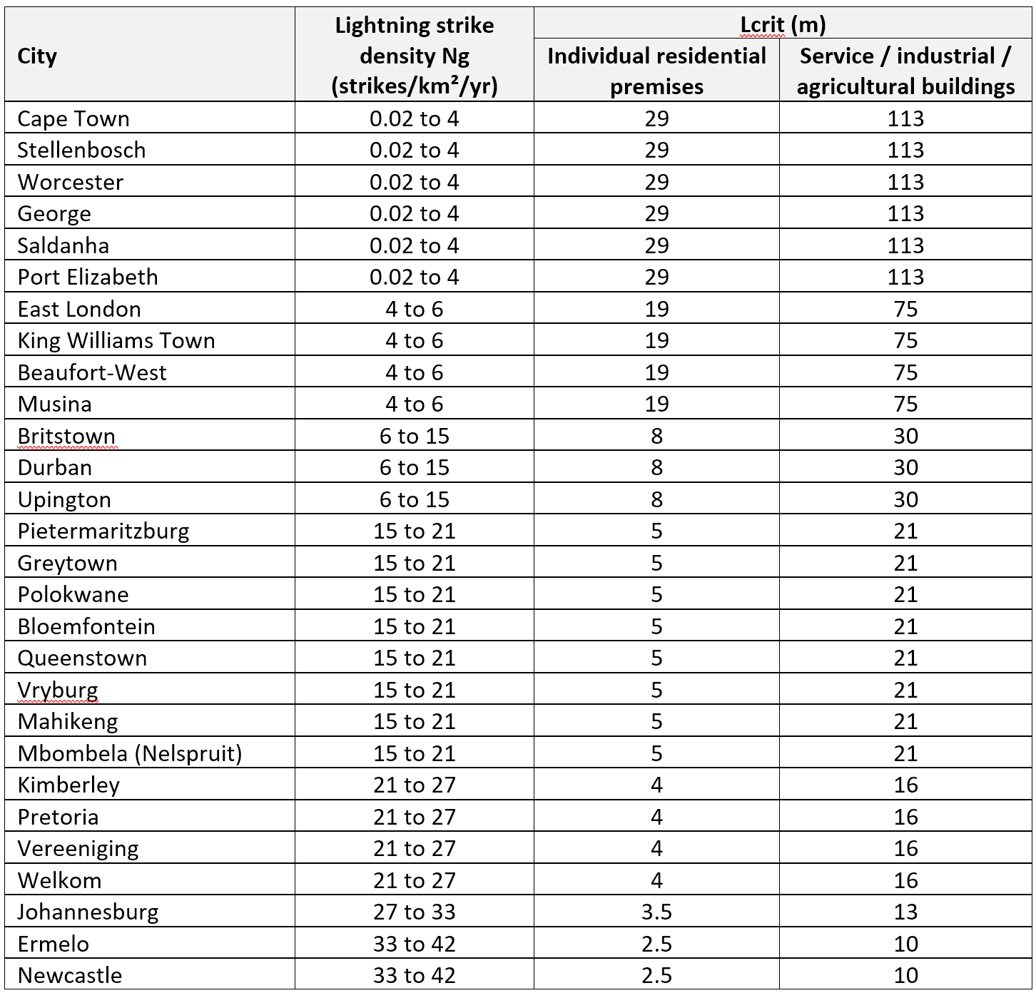
Appendix G. IEC/SANS and EMC Test Certificates: Elon® 100


Appendix H. Warranty
If the PowerOptimal Elon® 100 (“the Product”) is found to be defective, you will be entitled to a repair or replacement within 2 (two) year of the date of delivery of the Product to you. Please keep your receipt as proof of purchase. If you are a consumer as defined in the Consumer Protection Act No. 68 of 2008 (“the CPA”), you will be entitled to such remedies as are made available under the CPA in relation to the return of goods.
PowerOptimal will not have any liability or obligation to you where the Product has been subjected to abuse, misuse, improper use, improper testing, negligence, accident, alteration, tampering or repair by a third party.
To the maximum extent permitted by applicable law, in no event shall PowerOptimal be liable for any special, incidental, indirect, or consequential damages whatsoever, including, without limitation, damages for loss of business profits or business interruption, arising out of the use or inability to use this product.
Please note that this unit must be installed by an electrical contractor registered with the Department of Labour. Failure to do so may invalidate this warranty. Please keep the CoC (Certificate of Compliance) issued by the electrical contractor on completion of the installation.
Appendix I. Terminology
AC Alternating Current – an electric current that reverses its direction many times a second at regular intervals, with voltage typically varying in the form of a sine wave.
CoC Certificate of Compliance – to be issued by the electrician installing your Elon® 100 system
CPA Consumer Protection Act No. 68 of 2008
DB Distribution board – the main electrical distribution board / panel in your home, containing circuit breakers and switches.
DC Direct Current – an electric current flowing in one direction only. Solar PV modules produce direct current electricity.
Geyser South African term for a water heater
IEC International Electrotechnical Commission
Impp The solar module current at maximum power point (MPP). Manufacturers usually report two Impp values: one at STC and one at NOCT.
kWh A derived unit of energy equal to 3.6 MJ (megajoules). The amount of energy used by a 1 kW electrical device over a period of 1 hour.
kWp or Wp The peak power rating in kilowatt (kW) or watt (W) of a solar module or array – i.e. the output power achieved under full solar radiation. This is usually reported at STC and NOCT.
MPP Maximum power point. This is the point on a solar cell, module or array’s power or I-V (current-voltage) curve that has the highest power output.
NOCT Nominal Operating Cell Temperature (also sometimes referred to as NMOT or Nominal Module Operating Temperature). This refers to the temperature that open circuited solar PV modules will reach under conditions that more closely match actual field operational conditions than STC. The modules are tested at 800 W/m² simulated solar irradiance, 20 °C ambient temperature, 1 m/s wind velocity and open back side mounting. Depending on the quality of the cell / module design, the NOCT can reach anything from 33 to 58 °C[6]. Since solar PV cell power output reduces with increase in temperature, a lower NOCT is better.
PV Photovoltaic – referring to the production of electric current at the junction of two materials exposed to light.
SANS South African National Standards
STC Standard Test Conditions for solar cells – 1000 W/m² simulated solar irradiance and 25 °C solar cell temperature, and an air mass 1.5 spectrum (AM1.5).
Vmpp The solar module voltage at maximum power point (MPP). Manufacturers usually report two Vmpp values: one at STC and one at NOCT.
Notes
-
CRSES (Centre for Renewable and Sustainable Energy Studies). Website: http://www.crses.sun.ac.za/files/research/publications/SolarGIS_GHI_South_Africa_width15cm_300dpi.png. Last accessed: 07/04/2017. ↑
-
Urban Energy Support. Website: http://www.cityenergy.org.za/uploads/resource_274.pdf. Last accessed: 07/04/2017. ↑
-
D’Orazio M et al. 2013. Performance assessment of different roof integrated photovoltaic modules under Mediterranean Climate. ↑
-
Image source: http://ohioline.osu.edu/factsheet/AEX-652-11. ↑
-
Evert CR, Gijben M. 2017. Official South African Lightning Ground Flash Density Map 2006 to 2017. ↑
-
Source: http://pveducation.org/pvcdrom/modules/nominal-operating-cell-temperature. ↑
PowerOptimal Elon 100 Installation Manual v1.40 (Elon 100 units pre-2019)

PLEASE NOTE: This manual is for old Elon® 100s up to August 2019.
See https://poweroptimal.com/manuals/ for manuals & guides for new Elons from September 2019 onwards.
(How do I know if I have an old or new Elon® 100? The controller for the old version says “Efficiency” below the dial (knob), whilst the controller for the new version has “Turn anticlockwise to increase solar hours” below the dial.)
Version date: 2019/09/19

SAFETY WARNING
- Installation of the Elon 100 should ONLY be performed by an electrical contractor registered with the Department of Labour (the so-called “wireman’s licence”) and strictly according to the installation instructions in this manual. The electrician should provide you with a Certificate of Compliance (CoC) once installation is completed.
- We strongly recommend that you use a reputable and experienced solar photovoltaic (PV) system installer to install your solar PV modules.
- Solar PV modules exposed to the sun are live (i.e. will produce electricity) and can give an electric shock. Special care should be taken and only trained solar PV installers should install the modules.
- Do not attempt to alter or service the electrical installation, or open the Elon 100 unit or controller for any purpose.
- Use the Elon 100 only for its intended purpose.
- Always make sure that every wiring connection is properly tightened.
- Do not earth either of the solar module wires (but do earth the frames).
- All installation wiring should be at least 2.5mm².
- Avoid coiling, since DC switching can create damaging spikes.
- Keep all wires as short as possible.
 Refer to the PowerOptimal website for the Elon 100 User Manual: www.poweroptimal.com/manuals
Table of Contents
1. Required tools
2. Basic wiring diagram
3. Solar PV array installation
4. Elon 100 installation
5. Element installation (retrofit)
Appendix A. Solar yield
A1. Solar irradiance levels
A2. Geographic features
A3. Azimuth / horizontal angle
A4. Inclination or tilt angle
A5. Shading
A6. Ambient temperature
Appendix B. Deciding on Size of Solar Array
Appendix C. PV array and geyser (water heater) element matching
Appendix D. Technical Specification Summary: Elon 100
Appendix E. IEC/SANS Test Certificate: Elon 100
Appendix F. Warranty
Appendix G. Terminology
Notes
1. Required tools
The following tools are required for the installation. Use insulated tools wherever applicable.
- Solar modules (mounting) - please refer to solar module / mounting installation instructions – the below is only a guideline:
- Cordless screwdriver with bits
- Drill
- Set of drill bits (wood, steel, stone)
- Set of screwdrivers
- Set of Allen (hex) keys
- Tape measure
- Grinder (tile roof installations)
- Permanent marker
- Chalk
- Hammer
- Solar modules (electrical):
- AC/DC Clamp meter
- Side-cutting pliers
- Screwdriver set
- Crimping tool
- 4 mm² wire (double insulated) (or other size as determined by solar PV voltage and wire length)
- Cable ties
- Elon 100 - the following additional tools:
- Drill or punch (to make holes for glands)
- 2.5 mm² panel wire
2. Basic wiring diagram
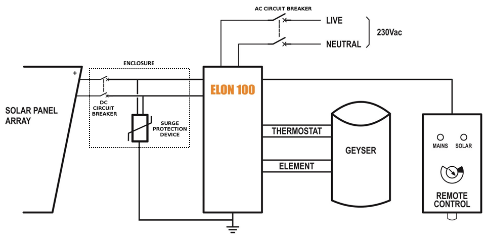
Note: Both AC & DC circuit breakers should be installed within 1.5m of the geyser (water heater), line of sight.
3. Solar PV array installation
Modules should only be installed by a trained solar PV installation technician. Array position and orientation have a major impact on power production (see Appendix A).
Review the instructions from your solar PV module supplier / manufacturer on installation.

Please note: A South African standard for low voltage embedded generation installations is being developed (SANS 10142:3). In the absence of this standard, your solar PV installation technician should follow SANS 10142:1 (Standard for low voltage installations) as always, and can refer to interim guidelines in anticipation of the SANS 10142:3 standard – see for example the document provided by PQRS:
SAPVIA (South African Photovoltaic Industry Association) has made available an excellent guide to solar PV installations. See:
https://www.pvgreencard.co.za/Solar%20PV%20Guidelines%20-%20Digital%20Spread%20High-res.pdf
NB: Refer to Appendices B & C for guidelines on selecting the right size solar PV array for the user requirements, and for correctly matching the solar PV array and the geyser element.
The below installation steps are a general guide only – refer to the abovementioned standards and guidelines.
- A very important starting point is safety gear: ensure that all installers wear a helmet and insulated safety gloves, as well as fall protection safety gear if work will be done on a roof or elevated area.
- The solar PV array should only consist of one string of 3 to 6 modules (60-cell) or 3 to 5 modules (72 cell) in series, or two parallel strings of 8 (2 x 4) or 10 (2 x 5) modules. Do not exceed the DC voltage or current ratings of the Elon 100 (220V DC and 20A DC) under any circumstances.
- Attach bracket / mounting structure to roof. Use mounting structure recommended by solar module supplier for roof type and size of solar modules.
- Fix the solar PV modules to the mounting structure whilst connecting the module cables to each other.
- If practical, cover the modules to ensure that there is no potential for electric shock whilst installing the system.
- Ground the mounting structure only.
- Install the wiring from the solar PV array to the Elon 100 unit in the ceiling space. Ensure circuit breakers / isolators are in the “Open” position. Installation of a Surge Protective Device (SPD) between the solar PV array and the Elon 100 is recommended.
- Last step is to connect the array to the rest of the wiring, making sure that both the positive and negative wires are fully isolated from ground and keeping circuit breakers / isolators in the “Open” position.
Some “DO’s & DON’T’s” when installing solar PV arrays:
Your solar PV installer should not make any of these basic mistakes, but they are listed here just in case.
- DO earth the PV array structure.
- DO isolate the wires from the PV array structure.
- DON’T use different sizes, types or specifications of modules together in the same string or array.
- DON’T install solar arrays where they will be partially shaded during any season of the year if it can be avoided at all.
- DO install the arrays so that there is space for inspection or maintenance when needed.
- DO use cabling of the correct size for your solar array.
- DON’T install the solar array flush with your rooftop. Use struts / brackets that ensure an unrestricted air gap of at least 40 mm between the roof and the modules.
- DON’T walk on the modules.
- DO ensure that connectors are kept clean and away from water.
- DON’T leave exposed modules in short circuit.
- DO ensure that all connectors are securely fastened.
- DON’T exceed the voltage ratings of any components.
- DO properly route and secure all cables.
- DON’T coil cables.
4. Elon 100 installation
- Isolate the geyser – switch off the geyser circuit breaker at the main electrical distribution board (DB) AND switch off the geyser isolator at the geyser.
- Confirm with a multimeter that there is no voltage across the wires.
- Install circuit breaker (or isolator and fuse) for solar PV (DC) supply. Also install AC supply isolator / circuit breaker if there is none. NB Ensure that the DC circuit breaker is rated for the DC voltage and current of the installed solar PV array.
- The circuit breakers / isolators must be installed within 1.5m of the geyser, and must be line of sight / visible (i.e. do not install them at the back of the geyser).
- The DC wires must not be earthed – i.e. they must be fully isolated from earth. Do NOT test with a Megger.
- Keep the DC wires as short as possible.
- Avoid any coils in DC wires.
- Recommended wiring size is at least 2.5 mm². Use panel wire for all connections to the Elon 100.
- Install the Elon 100 unit according to wiring diagram (see Section 2).
- Mount the Elon 100 unit close to the geyser and protect from outside elements.
- Mount the controller (remote control) inside or next to the main DB in the house or in another convenient and accessible location (for example the garage). Double-sided mounting tape and Genkem contact adhesive work well for most surfaces.
- Connect the Elon 100 and thermostat last.

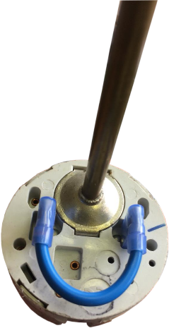
Note: As per the wiring diagram, the thermostat and element should be connected to the Elon SEPARATELY (independently). For TSE and Thermowatt (RTS) thermostats, connect the Elon directly to the two screw terminals and short the two male terminals at the bottom together, using the bridging wire with female connectors supplied with the Elon 100 (see photos above). (Less then 20 mA DC current will flow through this wire – it is a sensing current only.) There must be no connection between the thermostat and the element.
10. Connect the two element terminals directly to the connectors marked “element” on the Elon. For flange-type elements, use the supplied wiring with element adapter (see photos below). For many elements, the female terminals are sunk too deep in the plastic cover, leading to poor connectivity. If this is the case, trim the tops of the plastic cover on the element so that it is flush with the tops of the female terminals. Make sure that the element adapter fits tightly into the element and that the two male connectors of the adapter are slotted correctly into the female terminals of the element. Crimp both terminals (you can do this through the plastic cover) to ensure a tight fit on both sides.
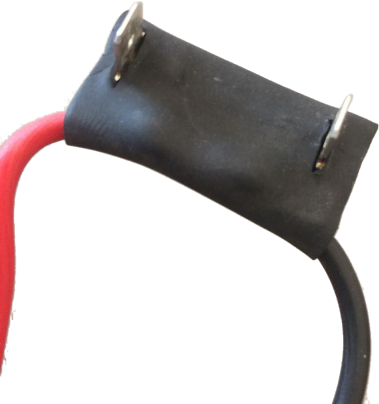
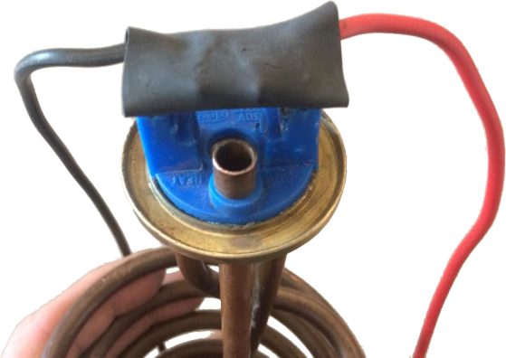
11. Slide the thermostat (with bridging wire installed) into the pocket in the element as deep as it can go.
12. Set the thermostat to the desired temperature (55 °C maximum).
13. Attach installation diagram sticker (as provided) close by the geyser in a clearly visible position. (Do not attach it directly to the geyser, as it will disappear if the geyser is replaced.)
14. Once installation is complete, do the following:
-
- Turn the control dial to "SOLAR ONLY".
- Switch on the AC & DC circuit breakers or isolators
- Remove the covering from the solar modules
- Switch on the geyser circuit breaker at the main DB.
15. Check that Elon 100 unit is operational (refer to LED lights on controller – see below).
-
- Confirm solar PV array supply voltage and DC power to geyser when thermostat is closed. The Elon 100 will switch DC power to the geyser approximately 10 to 15 seconds after DC power to the Elon has been switched on (if there is enough sunlight). (If thermostat is not closed, open hot water tap in house until it closes.)
- Test mains override by pressing and holding the override button for 5 seconds. The red light should start flashing (except if geyser is already at thermostat setpoint temperature). NOTE THAT THE ELON WILL NOT SWITCH TO MAINS WITHIN 5 MINUTES OF MAINS POWER SWITCH-ON OR RECONNECTION. This is to allow grid power to stabilize after a power failure.
- Confirm that no power is supplied to geyser element when thermostat is open (turn thermostat set point to lowest setting).
16. Set controller dial to desired control position (6 o’clock is good for an initial setting).
Note: if doing any maintenance, rewiring or disconnecting the Elon 100 or geyser element for any reason, it is good practice to first switch off both the AC & DC circuit breakers / isolators, and then disconnect one of the wires between the Elon 100 and thermostat before disconnecting the rest of the wires.
The Mains & solar indicator lights indicate the following conditions:
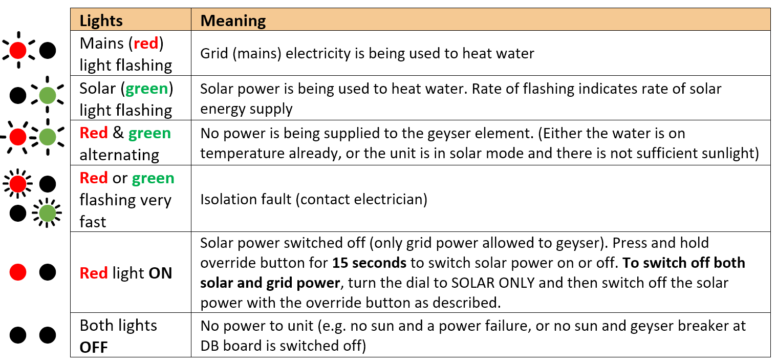
Controller settings for switching off solar or grid power to electric geyser
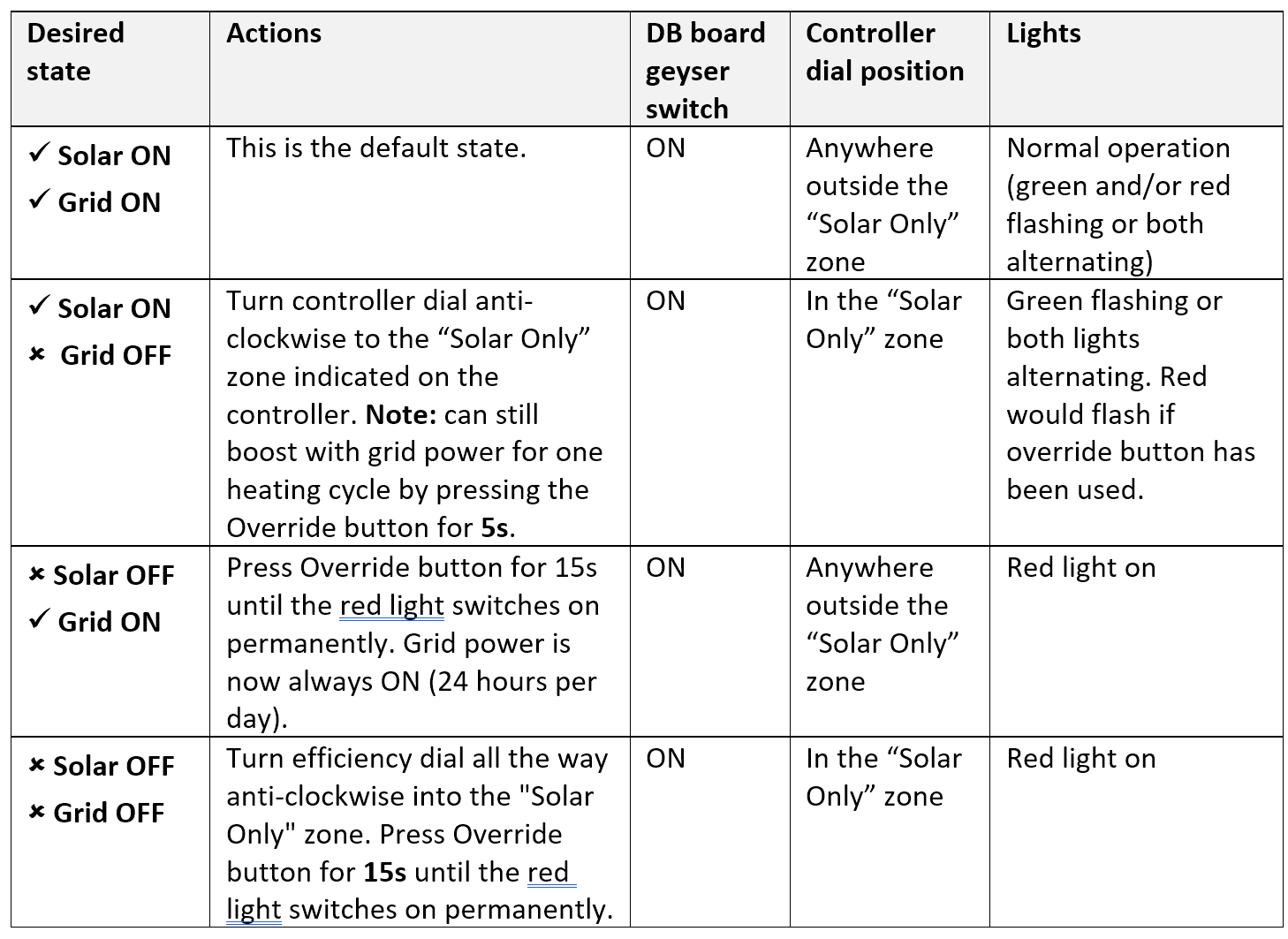
5. Element installation (retrofit)
If you need to exchange the element on an existing geyser, please follow the instructions provided by the element supplier.
There are two main types of geyser heating elements: screw-in and flange type. There are also two main types of thermostats: VKF-11 and TSE. The below table provides a guide to Elon compatibility with the different elements and thermostats.
|
Element type |
Compatible thermostat type |
Comments |
|---|---|---|
|
Screw-in element:
|
VKF-11 thermostat:
|
Element & thermostat have separate electrical connections, so each can be connected (wired) separately to the Elon. Thus, this element-thermostat combination is directly compatible with the Elon. (No need to use the bridging wire or element adapter supplied with the Elon unit.) The thermostat pocket in the element is the right size for the VKF-11 thermostat. |
|
Spiral element (flange type) with smaller diameter thermostat pocket: 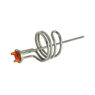 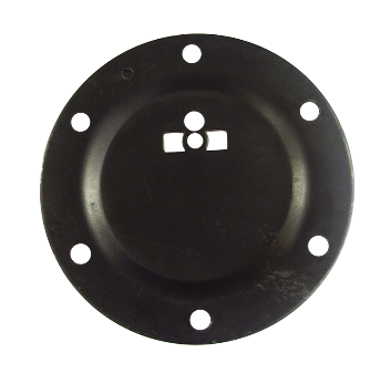 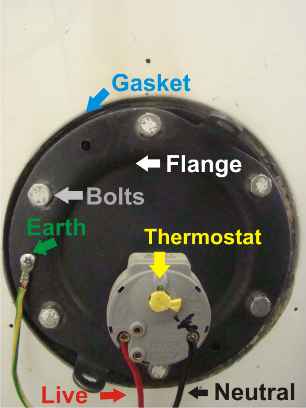 |
TSE thermostat: Thermowatt (RTS) thermostat: 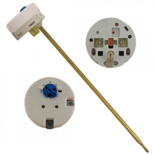  |
The spiral element generally has a smaller thermostat pocket than the screw-in element. The TSE and Thermowatt (RTS) thermostats fit into this smaller pocket. The VKF-11 thermostat requires a larger pocket and does not fit into standard spiral element pockets. The TSE and Thermowatt thermostats normally clip directly into the element, but this won’t be the case when the Elon is connected. Use the bridging wire and element adapter supplied with the Elon (see Figures 4.1 to 4.4 above) to connect the Elon to these thermostats and elements. |
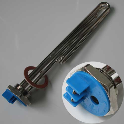
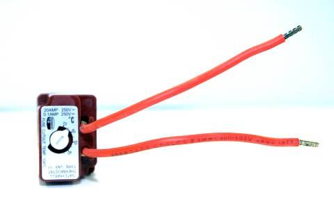
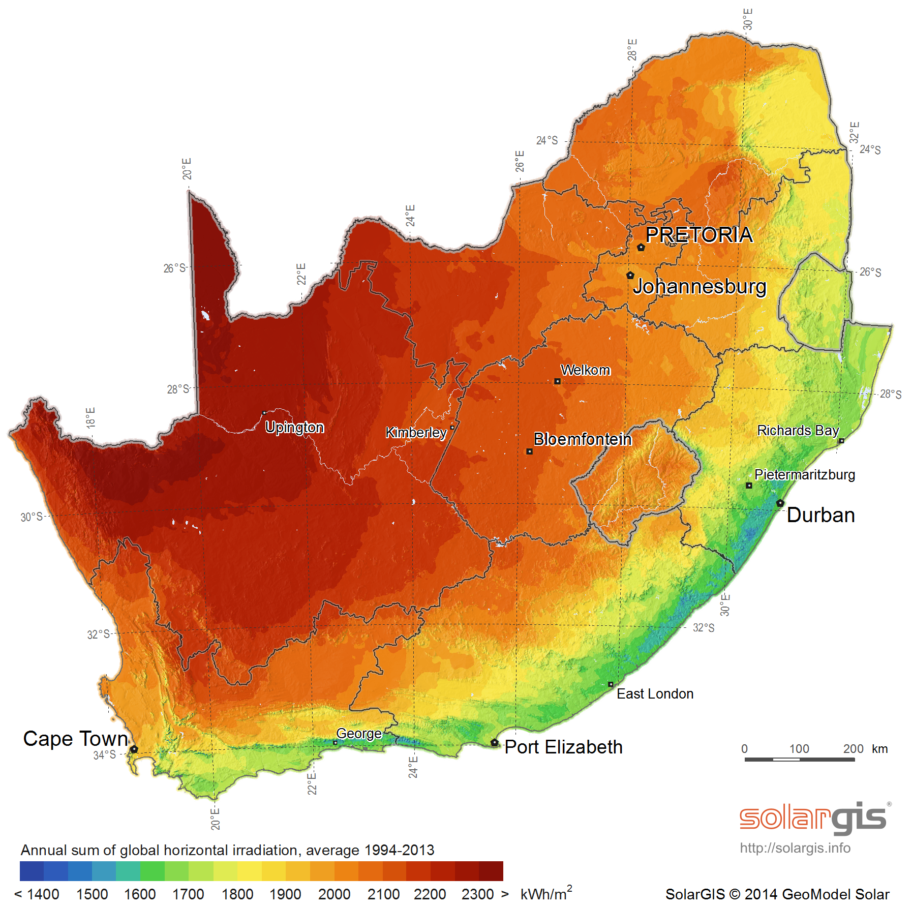
Appendix A. Solar yield
Note: only basic information is provided here. Your solar PV installation technician should advise on the best configuration for your specific location, roof structure, etc.
The yield produced by solar PV modules depends on a number of factors:
- Solar irradiance levels at your location (which varies with time of day, season and weather conditions)
- Geographic features at your location (e.g. mountains or buildings causing morning or afternoon shade)
- Azimuth and tilt of the modules
- Shading
- Ambient temperature (also influenced by wind)
A1. Solar irradiance levels
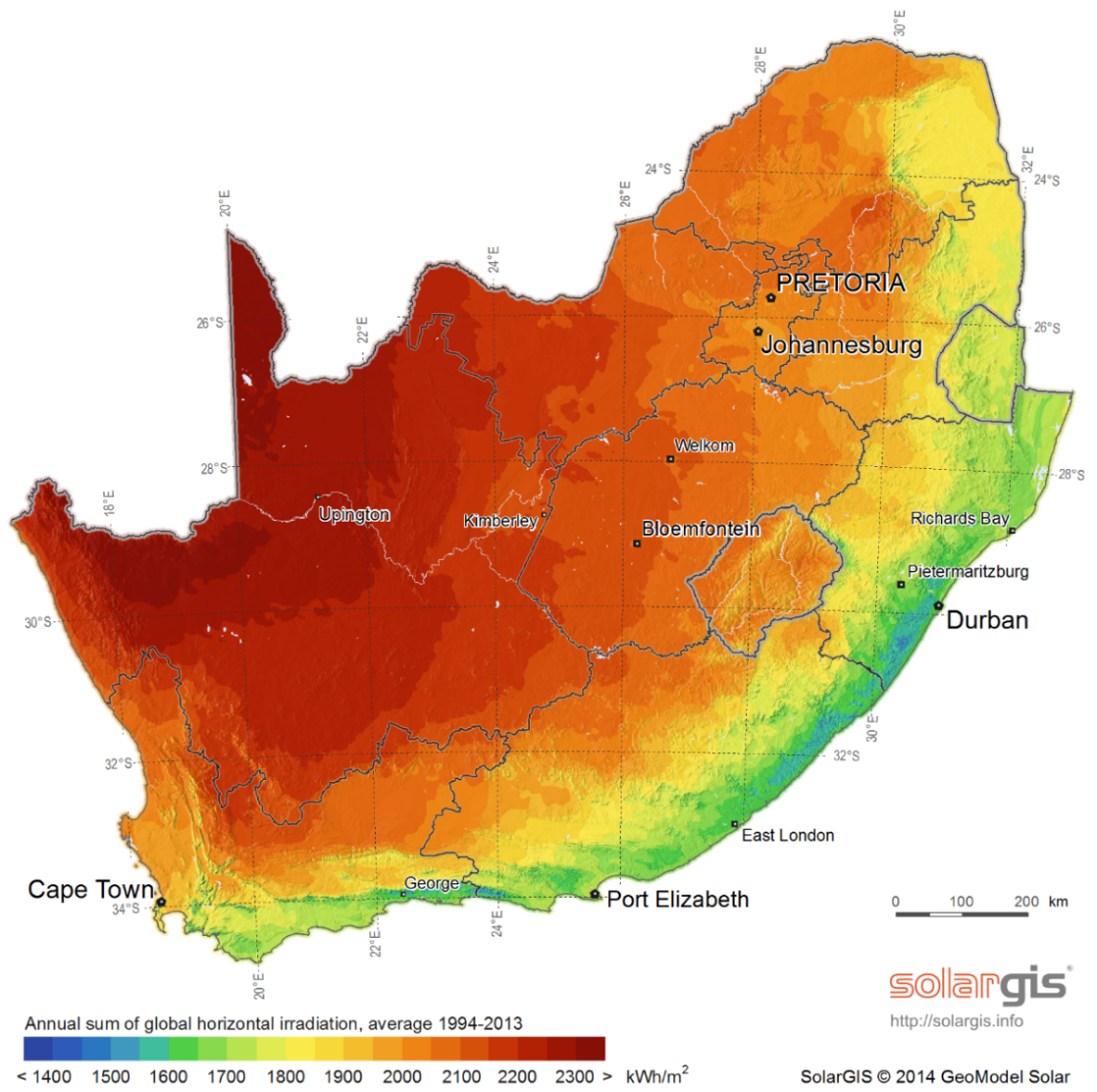 The map below shows the general solar irradiance levels (GHI or Global Horizontal Irradiance) in South Africa[1]:
You can expect the following approximate energy generation from solar modules for various locations[2]:
|
Location |
Electricity generated kWh/kWp per year |
|
Bloemfontein |
2055 |
|
Cape Town |
1762 |
|
Durban |
1570 |
|
Johannesburg / Pretoria |
1871 |
|
Mbombela |
1766 |
|
Port Elizabeth |
1698 |
|
Upington |
2075 |
A2. Geographic features
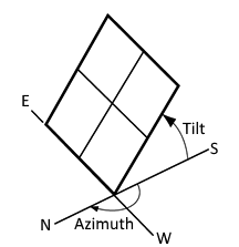 Major geographical features (such as hills or mountains) can reduce the total solar yield.
A3. Azimuth / horizontal angle
The azimuth refers to the horizontal orientation of the modules – in the Southern Hemisphere, by how many degrees they are oriented away from north
Due north is best in the Southern hemisphere. Modules should preferably not be oriented more than 15º away from due north.
A4. Inclination or tilt angle
The tilt angle refers to the vertical orientation of the modules – a rough guide is that the modules should be tilted at the site’s latitude. For example, Musina is 22º S, Pretoria & Johannesburg are 26º S, Bloemfontein is 29º S, Durban is 30º S and Cape Town & Port Elizabeth are 34º S. To optimise winter performance, one can add 15º to the tilt angle. (Note: as long as you are within about 15º of the optimal latitude, the loss in efficiency is not substantial.)
A5. Shading
Solar modules lose a lot of efficiency if even a small part of the module is shaded. For example, just 3% shading can cause a 25% loss in power! Shaded cells on a module also causes hotspots, which will reduce module lifetime.
It is thus important to place the solar modules on a rooftop area that is free from shading for as much as possible of the day (and throughout the year).
A6. Ambient temperature
Solar PV modules’ performance decreases with increasing temperature. Wind will reduce the temperature of the solar array and will thus improve performance. Thus, it is important to install rooftop solar modules with an air gap of at least 40 mm between the modules and roof[3].
Appendix B. Deciding on Size of Solar Array
Terminology used
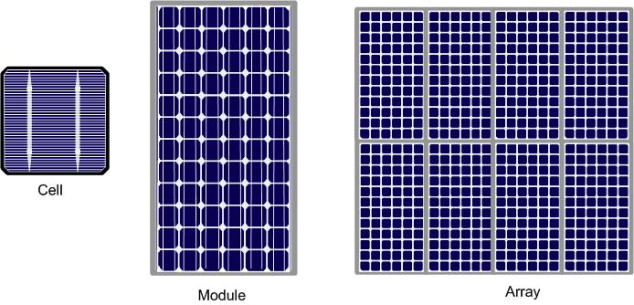
Solar power is generated by solar cells, which are arranged in framed modules, typically of 60 or 72 cells each. The total set of solar PV modules installed is referred to as a solar PV array[4].
The table below provides a basic guide to selecting the size of the Elon system based on number of people in the household and/or hot water use. Read on for a more detailed guide.
TABLE B1. ANNUAL AVERAGE LITRES OF WATER HEATED PER DAY
The below example table indicates the average number of litres of water per day that the system will heat from 15 to 60 °C over a year period for different solar array peak power ratings. (The amount of water heated will vary with weather conditions, by geographic location and by season. Water heated per day will be significantly lower in winter and significantly higher in summer. These numbers indicate heating capacity – i.e. if no hot water is used on a given day, there will be less water heated on that day. This is only an approximate guide.)
Example:
For a solar array of 1.2 kWp, an installation in Johannesburg would yield about 1724 kWh/kWp/yr, or 1724 x 1.2 kWp = 2069 kWh/yr. This would be sufficient to heat on average 109 litres of water per day. For a family of 2 each using 80 litres of hot water per day, this would provide about 109 ÷ (80 x 2) or 68% of the annual hot water requirement.
TABLE B2. ANNUAL AVERAGE NUMBER OF SHOWERS PER DAY
The below table indicates the average number of showers per day for which the system will supply hot water over a year period for different solar array peak power ratings. (The amount of water heated will vary with weather conditions, by geographic location and by season. Water heated per day will be significantly lower in winter and significantly higher in summer. These numbers indicate heating capacity – i.e. if no hot water is used on a given day, there will be less water heated on that day. This is only an approximate guide.)
The table is based on 6-minute showers at 40 °C and 8 litres/min low flow showerheads. Old showerheads can use up to 15 litres/min and would substantially reduce the number of showers.
Example:
For a solar PV array of 2.5 kWp, an installation in Johannesburg would yield about 1724 kWh/kWp/yr, or 1724 x 2.5 kWp = 4 310 kWh/yr. This would be sufficient for about 6 to 7 showers per day.
TABLE B3. PERCENTAGE OF ANNUAL HOT WATER REQUIREMENT
The below example table indicates what % of the annual hot water requirement will on average be supplied by the system for 2 people each using 80 litres of hot (60 °C) water per day. (The amount of water heated will vary with weather conditions, by geographic location and by season. Water heated per day will be significantly lower in winter and significantly higher in summer. These numbers indicate heating capacity – i.e. if no hot water is used on a given day, there will be less water heated on that day. This is only an approximate guide.)
Examples:
An array of 1.2 kWp will provide approximately 64% of the annual hot water requirement for a family of two people in Cape Town.
An array of 2 kWp will provide approximately 124% x (4 / 2) = 62% of the annual hot water requirement for a family of four people in Bloemfontein.
TABLE B4. PEAK POWER OUTPUT FOR VARIOUS SOLAR MODULES AND ARRAY SIZES
The peak power production (Wp) of the modules at STC (Standard Test Conditions) and at NOCT (Nominal Operating Cell Temperature) are provided by the solar PV module manufacturer. The below table indicates the peak power at STC for a range of solar module power ratings and array sizes.
|
No. of cells per module |
Module STC power rating (Wp) |
Total peak power at STC in kWp for an array of X modules |
||||||
|---|---|---|---|---|---|---|---|---|
|
3 modules |
4 modules |
5 modules |
6 modules |
2 x 4 (8) modules |
2 x 5 (10) modules |
2 x 6 (12) modules |
||
|
60 |
250 |
0.75 |
1.00 |
1.25 |
1.50 |
2.00 |
2.50 |
3.00 |
|
60 |
255 |
0.77 |
1.02 |
1.28 |
1.53 |
2.04 |
2.55 |
3.06 |
|
60 |
260 |
0.78 |
1.04 |
1.30 |
1.56 |
2.08 |
2.60 |
3.12 |
|
60 |
265 |
0.80 |
1.06 |
1.33 |
1.59 |
2.12 |
2.65 |
3.18 |
|
60 |
270 |
0.81 |
1.08 |
1.35 |
1.62 |
2.16 |
2.70 |
3.24 |
|
60 |
275 |
0.825 |
1.10 |
1.375 |
1.65 |
2.20 |
2.75 |
3.30 |
|
60 |
280 |
0.84 |
1.12 |
1.40 |
1.68 |
2.24 |
2.80 |
3.36 |
|
60 |
285 |
0.855 |
1.14 |
1.425 |
1.71 |
2.28 |
2.85 |
3.42 |
|
60 |
290 |
0.87 |
1.16 |
1.45 |
1.74 |
2.32 |
2.90 |
3.48 |
|
72 |
295 |
0.885 |
1.18 |
1.475 |
1.77 |
2.36 |
2.95 |
3.54 NOT ALLOWED (exceeds maximum rated Elon 100 voltage) |
|
72 |
300 |
0.90 |
1.20 |
1.50 |
1.80 |
2.40 |
3.00 |
3.60 |
|
72 |
305 |
0.915 |
1.22 |
1.525 |
1.83 NOT ALLOWED (exceeds maximum rated Elon 100 voltage) |
2.44 |
3.05 |
3.66 |
|
72 |
310 |
0.93 |
1.24 |
1.55 |
1.86 |
2.48 |
3.10 |
3.72 |
|
72 |
315 |
0.945 |
1.26 |
1.575 |
1.89 |
2.52 |
3.15 |
3.78 |
|
72 |
320 |
0.96 |
1.28 |
1.60 |
1.92 |
2.56 |
3.20 |
3.84 |
|
72 |
325 |
0.975 |
1.30 |
1.625 |
1.95 |
2.60 |
3.25 |
3.90 |
|
72 |
330 |
0.99 |
1.32 |
1.65 |
1.98 |
2.64 |
3.30 |
3.96 |
|
72 |
335 |
1.005 |
1.34 |
1.675 |
2.01 |
2.68 |
3.35 |
4.02 |
|
72 |
340 |
1.02 |
1.36 |
1.70 |
2.04 |
2.72 |
3.40 |
4.08 |
Examples:
An array of 4 x 300 Wp modules in series will have a total peak power (at STC) of 1.2 kWp.
An array of 2 parallel strings of 5 modules of 280 Wp each (10 modules of 280 Wp in total) will have a total peak power (at STC) of 2.8 kWp.
Appendix C. PV array and geyser (water heater) element matching
TABLE C1. PV ARRAY AND GEYSER (WATER HEATER) ELEMENT MATCHING
It is important to match PV array specifications and heating elements for maximum power transfer efficiency. See the below table for the recommended heating element power rating for different solar module power ratings and array sizes.
DO NOT DEVIATE FROM THE RECOMMENDED ARRAY-ELEMENT MATCHING CONFIGURATIONS WITHOUT CONSULTING POWEROPTIMAL.
Appendix D. Technical Specification Summary: Elon 100
Refer to the PowerOptimal website for the full Technical Specification www.poweroptimal.com/specifications
|
Rated input voltage |
250V AC, 220V DC |
|
Rated input current |
25A AC, 20A DC |
|
Mains (AC) voltage range |
-50% to +100% (but will disconnect all loads when breach is greater than +/- 15%) |
|
System power supply |
Solar or 230V AC mains |
|
Shutdown |
Sufficient power supply capacity to manage processor, switching and data storage if both mains and solar supply fail |
|
Solar voltage |
20 – 220 V DC |
|
Solar energy availability |
Automatically determines availability of sufficient solar energy before supplying load from solar modules |
|
Efficiency control |
Can be adjusted to run from “solar only” to substantial AC mains power usage |
|
Override switch |
A request (override) switch to force the managed load to use AC mains for one heating cycle is provided |
|
Thermostat |
Uses the standard normally open thermostat switch associated with the geyser element as a sensor only, with less than 10mA sense current, to control power to the element |
|
Reverse polarity protection |
Protected against reverse connection of solar array |
|
Switching timing |
Built-in random numbers generation staggers switching times where more than one Elon 100 is deployed |
|
Enclosure ingress protection rating |
IP65 |
|
Annual energy production compared to inverter-based system |
> 90% when solar array and geyser element are matched correctly |
It is important to match modules and heating elements for maximum power transfer efficiency. See the tables in Appendix C for the recommended heating element power rating for different solar module specifications and array configurations.
Appendix E. IEC/SANS Test Certificate: Elon 100
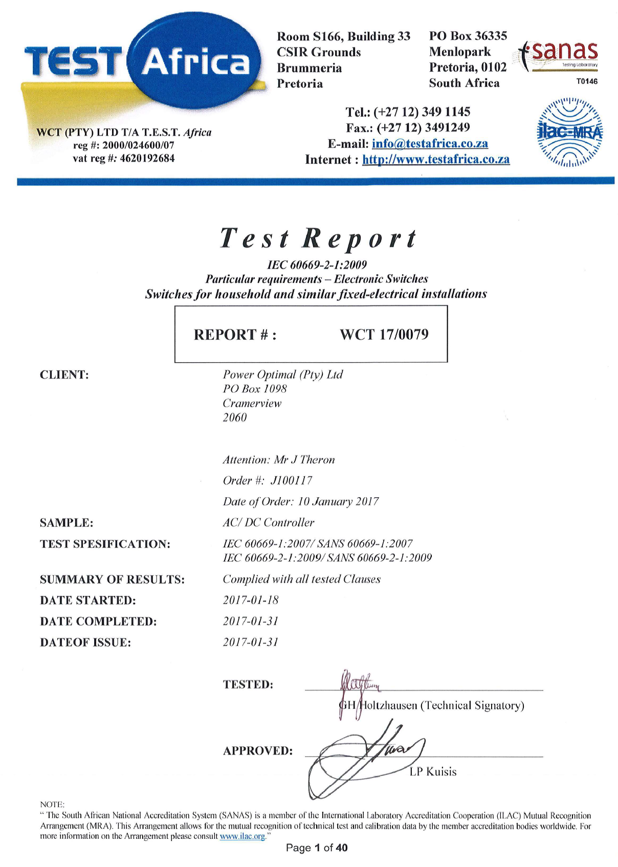
Appendix F. Warranty
If the PowerOptimal ElonTM 100 (“the Product”) is found to be defective, you will be entitled to a repair or replacement within 2 (two) years of the date of delivery of the Product to you. Please keep your receipt as proof of purchase. If you are a consumer as defined in the Consumer Protection Act No. 68 of 2008 (“the CPA”), you will be entitled to such remedies as are made available under the CPA in relation to the return of goods.
PowerOptimal will not have any liability or obligation to you where the Product has been subjected to abuse, misuse, improper use, improper testing, negligence, accident, alteration, tampering or repair by a third party.
To the maximum extent permitted by applicable law, in no event shall PowerOptimal be liable for any special, incidental, indirect, or consequential damages whatsoever, including, without limitation, damages for loss of business profits or business interruption, arising out of the use or inability to use this product.
Please note that this unit must be installed by an electrical contractor registered with the Department of Labour. Failure to do so may invalidate this warranty.
Appendix G. Terminology
AC Alternating Current – an electric current that reverses its direction many times a second at regular intervals, with voltage typically varying in the form of a sine wave.
CoC Certificate of Compliance – to be issued by the electrician installing your Elon 100 system
CPA Consumer Protection Act No. 68 of 2008
DB Distribution board – the main electrical distribution board / panel in your home, containing circuit breakers and switches.
DC Direct Current – an electric current flowing in one direction only. Solar PV modules produce direct current electricity.
Geyser South African term for a water heater
IEC International Electrotechnical Commission
Impp The solar module current at maximum power point (MPP). Manufacturers usually report two Impp values: one at STC and one at NOCT.
kWh A derived unit of energy equal to 3.6 MJ (megajoules). The amount of energy used by a 1 kW electrical device over a period of 1 hour.
kWp or Wp The peak power rating in kilowatt (kW) or watt (W) of a solar module or array – i.e. the output power achieved under full solar radiation. This is usually reported at STC and NOCT.
MPP Maximum power point. This is the point on a solar cell, module or array’s power or I-V (current-voltage) curve that has the highest power output.
NOCT Nominal Operating Cell Temperature. This refers to the temperature that open circuited solar PV modules will reach under conditions that more closely match actual field operational conditions than STC. The modules are tested at 800 W/m² simulated solar irradiance, 20 °C ambient temperature, 1 m/s wind velocity and open back side mounting. Depending on the quality of the cell / module design, the NOCT can reach anything from 33 to 58 °C[5]. Since solar PV cell power output reduces with increase in temperature, a lower NOCT is better.
PV Photovoltaic – referring to the production of electric current at the junction of two materials exposed to light.
SANS South African National Standards
STC Standard Test Conditions for solar cells – 1000 W/m² simulated solar irradiance and 25 °C solar cell temperature, and an air mass 1.5 spectrum (AM1.5).
Vmpp The solar module voltage at maximum power point (MPP). Manufacturers usually report two Vmpp values: one at STC and one at NOCT.
Notes
-
CRSES (Centre for Renewable and Sustainable Energy Studies). Website: http://www.crses.sun.ac.za/files/research/publications/SolarGIS_GHI_South_Africa_width15cm_300dpi.png. Last accessed: 07/04/2017. ↑
-
Urban Energy Support. Website: http://www.cityenergy.org.za/uploads/resource_274.pdf. Last accessed: 07/04/2017. ↑
-
D’Orazio M et al. 2013. Performance assessment of different roof integrated photovoltaic modules under Mediterranean Climate. ↑
-
Image source: http://ohioline.osu.edu/factsheet/AEX-652-11. ↑
-
Source: http://pveducation.org/pvcdrom/modules/nominal-operating-cell-temperature. ↑
PowerOptimal Elon 100 User Manual v1.40 (Elon 100 units pre-2019)

PLEASE NOTE: This manual is for old Elon® 100s up to August 2019.
See https://poweroptimal.com/manuals/ for manuals & guides for new Elons from September 2019 onwards.
(How do I know if I have an old or new Elon® 100? The controller for the old version says “Efficiency” below the dial (knob), whilst the controller for the new version has “Turn anticlockwise to increase solar hours” below the dial.)
Version date: 2019/07/02

SAFETY WARNING
- Installation of the Elon 100 should ONLY be performed by an electrical contractor registered with the Department of Labour (the so-called “wireman’s licence”) and strictly according to the installation instructions in this manual. The electrician should provide you with a Certificate of Compliance (CoC) once installation is completed.
- We strongly recommend that you use a reputable and experienced solar photovoltaic (PV) system installer to install your solar PV modules.
- Solar PV modules exposed to the sun are live (i.e. will produce electricity) and can give an electric shock. Special care should be taken and only trained solar PV installers should install the modules.
- Do not attempt to alter or service the electrical installation, or open the Elon 100 unit or controller for any purpose.
- Use the Elon 100 only for its intended purpose.
- Always make sure that every wiring connection is properly tightened.
- Do not earth either of the solar module wires (but do earth the frames).
- All installation wiring should be at least 2.5mm².
- Avoid coiling, since DC switching can create damaging spikes.
- Keep all wires as short as possible.
Refer to the PowerOptimal Elon 100 Installation Guide at www.poweroptimal.com/manuals for detailed installation information.
![]() You can find an easy-to-understand Quick Reference User Guide for download from: www.poweroptimal.com/manuals
You can find an easy-to-understand Quick Reference User Guide for download from: www.poweroptimal.com/manuals
You can also watch an online instruction video for instructions on how to use the PowerOptimal Elon® 100:
![]()
Table of Contents
1.3 Deciding on size of Elon system (basic guide)
2.2 Mains / solar indicator lights
2.5 Controller settings for switching off solar or grid power to electric geyser
2.6 How to maximise your savings
3.1 Solar PV module maintenance
4. What to expect in terms of performance
4.2 Impact of location and seasons
Appendix A. IEC/SANS Test Certificate: Elon 100
1. Introduction
Thank you for buying the PowerOptimal ElonTM 100 solar PV water heating unit! You can look forward to many years of savings and free energy from the sun.
1.1 System overview
The PowerOptimal Elon 100 operates on a very simple principle: it enables direct current (DC) electricity produced by solar PV modules to be used directly for water heating using a standard geyser with alternating current (AC) heating element and AC thermostat, with no need for an inverter. It uses the water in your geyser as a battery to store solar energy in the form of heat.
You can connect the system completely off-grid, or connect it to your existing grid AC power supply. Connecting the system to the existing grid supply allows for grid power backup in case of cloudy / overcast days, or where your hot water use exceeds the generation capacity of your solar PV array.
Note: the system is designed in such a way that there is no possibility of solar array-produced electricity feeding back into the grid.
Below is a simplified layout of the main components of the water heating system.

An array of solar modules (a string of 3 to 6 solar modules connected in series, or two parallel strings of 4, 5 or 6 solar modules each) is connected to the Elon 100. Grid electricity is also connected to the Elon 100.
The Elon 100 is connected to the geyser element and thermostat.
When the solar modules are producing electricity, the Elon 100 feeds this into the geyser element to heat water, until the water reaches the temperature setting on the thermostat.
Depending on the Elon 100 efficiency setting (see Section 2.3) or when the user presses the override button, the Elon 100 will boost the water heating with grid electricity.
1.2 Main system components
The main components of the system are as follows:
- Solar modules with struts, brackets and cabling
- PowerOptimal Elon unit with controller
- Existing or new water heater or geyser (hot water tank with AC heating element and AC thermostat)
- Isolators for grid and solar connections
1.3 Deciding on size of Elon system (basic guide)
The table below provides a basic guide to selecting the size of your Elon system based on number of people in the household and/or hot water use. The Installation Manual (which you can download from www.poweroptimal.com/manuals) contains a more detailed guide.
2. Operation
![]()
Instruction video: www.poweroptimal.com/elon100
Refer to our easy to understand instruction video on how to use the Elon 100.
2.1 Elon 100 controller
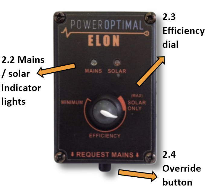
Your Elon 100 has a controller that is typically installed next to your DB (distribution board). The controller has three main functions:
- Indicating heating activity through the mains (red) & solar (green) indicator lights (Section 2.2)
- Setting the timing on the efficiency dial (Section 2.3)
- Forcing the system to use grid (mains) electricity for one heating cycle using the override button. (Section 2.4)
2.2 Mains / solar indicator lights
The Mains & solar indicator lights indicate the following conditions:
2.3 Efficiency dial
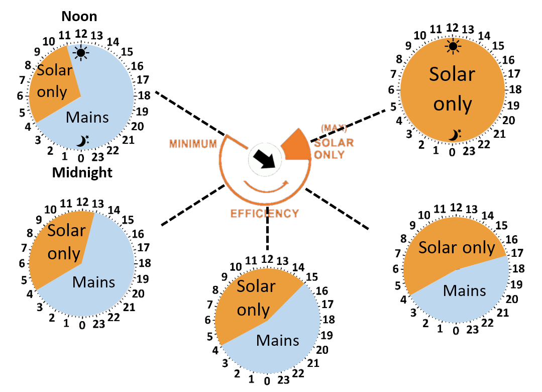
Turn the dial on the controller to set how much of the day the unit will run on solar power only (see the diagram above). It is generally best to just leave it pointing straight down.
The best setting for you will be determined by your hot water use habits and the number of solar PV panels installed.
At all dial settings except “Solar only”, the Elon 100 will switch off grid power to the geyser early in the morning. You will start with hot water in the geyser, but as you use it, the temperature will gradually drop, so that the geyser is ready to be heated by the sun during the day.
The dial determines at approximately what time the Elon will switch back to grid power, as shown in the diagram above.
At the “MINIMUM” efficiency setting, the Elon 100 will switch back to grid power around 11 am or 12 pm. As you turn the dial anti-clockwise, the time that the Elon 100 will switch back to grid power moves later and later in the day. This will give the solar power supply more time to heat the water before boosting with grid power.
So if you only use hot water early morning and in the evenings, you can set it close to “Solar only” to benefit from a longer solar energy heating period.
When the efficiency dial is set to “SOLAR ONLY”, the Elon 100 will ONLY use solar power to heat water.
Note that the override button is still functional at the “SOLAR ONLY” setting, in case you need to boost water heating on a cloudy day or when using a lot of hot water.
If you set the Elon efficiency setting to “SOLAR ONLY” (highest efficiency), you can increase the geyser thermostat temperature to 60 ºC to get maximum benefit from your solar array installation. We do not recommend setting the thermostat temperature above 60 °C. Remember to reduce the thermostat temperature again if you reduce the efficiency setting.

Warning: Do not set thermostat temperature above 65 ºC due to increased scalding risk. Be careful when opening hot water taps located close to your geyser. You can install a thermostatic mixing valve to reduce the risk of scalding – ask your plumber.
2.4 Override button
If you would like to override the functioning of the Elon 100 and force it to use grid power for water heating (for example in case of prolonged cloudy weather, or having used a lot of hot water), press and hold the override button for 5 seconds.
This will force the Elon 100 to switch to grid (mains) power for one heating cycle (in other words, it will the water with grid electricity to the thermostat set point from whatever temperature it is at the time of pressing the override button).
Only the red mains light on the controller should start flashing at this point. (If both red and green lights are flashing (alternating), the water is already at the thermostat set point, and pressing the override button will have no effect.)
To switch off solar power completely, press and hold the override button for 15 seconds. The red mains light will come on permanently. This means that the system is heating water with mains power 24 hours a day. To switch the solar power back on, again press and hold the override button for 15 seconds.
2.5 Controller settings for switching off solar or grid power to electric geyser
|
Desired state |
Actions |
DB board geyser switch |
Controller dial position |
Lights |
|
✓ Solar ON ✓ Grid ON |
This is the default state. |
ON |
Anywhere outside the “Solar Only” zone |
Normal operation (green and/or red flashing or both alternating) |
|
✓ Solar ON 🗶 Grid OFF |
Turn controller dial anti-clockwise to the “Solar Only” zone indicated on the controller. Note: can still boost with grid power for one heating cycle by pressing the Override button for 5s. |
ON |
In the “Solar Only” zone |
Green flashing or both lights alternating. Red would flash if override button has been used. |
|
🗶 Solar OFF ✓ Grid ON |
Press Override button for 15s until the red light switches on permanently. Grid power is now always ON (24 hours per day). |
ON |
Anywhere outside the “Solar Only” zone |
Red light on |
|
🗶 Solar OFF 🗶 Grid OFF |
Turn efficiency dial all the way anti-clockwise into the "Solar Only" zone. Press Override button for 15s until the red light switches on permanently. |
ON |
In the “Solar Only” zone |
Red light on |
2.6 How to maximise your savings
Efficiency dial
The best way to maximise your savings is to set the Elon efficiency dial to “SOLAR ONLY”. This will ensure that the unit will never use grid (mains) power for heating water. You can still override / boost with mains power (for example on a cloudy day) using the override button as described above.
If you do not have enough solar power for the number of people and overall level of hot water use in the household, you might not reach the desired water temperature with the “SOLAR ONLY” setting, and might need to reduce the efficiency setting, or reduce your hot water use.
Please note: The water in your geyser should be heated to 60 °C at least once a week to prevent Legionella bacterial growth[1]. If you have heavily overcast weather for more than a week, use the override button to supplement the solar water heating with grid electricity to reach the thermostat temperature setting.
When is the best time to shower?
If the efficiency dial is set to “SOLAR ONLY”, it is best for people in the household to shower either in the morning or in the evening, but not both. (If you shower in the evening, cold water will mix with the remaining warm water overnight, and you will have cold water the next morning. If you do not shower again in the morning, the water will be heated during the day.)
If the efficiency dial is set to lower efficiency than “SOLAR ONLY”, it is best to shower in the morning for maximum savings.
Going on holiday
If you are going on holiday, you don’t need to switch off the solar power supply to your geyser. It will continue to maintain water temperature and prevent or minimize Legionella bacteria growth. As a plus you will have hot water in your geyser when you return from holiday!
You can switch off the mains power supply to the geyser in one of two ways: (1) turn the Elon 100 efficiency dial to solar only (anti-clockwise to end position); OR (2) switch off the geyser circuit breaker in your electrical distribution board (DB). We recommend option 1.
If you do want to switch off both the solar and mains power supply to your geyser, turn the Elon 100 efficiency dial to solar only (anti-clockwise to end position), then press and hold the override button for 15 seconds (until the red light comes on permanently). Don’t switch off the circuit breaker at the DB board. (When you return, set the efficiency dial in its normal position, then press and hold the override button for 15 seconds until the red light switches off or starts flashing.)
General hot water energy saving tips
- Shower, don’t bath
- Install water-saving / low flow shower heads (these also save energy because of reduced hot water use!)
- Reduce shower duration
- Check that your geyser is well insulated
South Africa is a water-scarce country – reducing hot water use saves both energy and water!
3. Maintenance
The Elon 100 has been designed to last for a very long time, and has no moving parts aside from two electrical relays. No maintenance is required on the Elon 100.
3.1 Solar PV module maintenance
It is recommended that a qualified electrician inspect your solar PV installation at least once a year.
- At least once a week, check whether any of the indicator lights are flashing rapidly. (This indicates an isolation fault – refer to Section 3.2.)
- Perform regular visual checks (at least once a year). Check for soiling or any visible damage to any of the modules.
- If the modules have been soiled by dirt, dust, debris, bird droppings or any other materials, use water only and a sponge or soft cloth to clean them. Do the cleaning early in the morning or late in the afternoon, as the modules are hot during the day. Avoid using a water jet that may leave streaks on the modules.
- Visually inspect cables for any degradation or loose fittings.
- Look for any shading problems, such as trees that may have grown.
- An electrician can check solar power production on a sunny day to ensure that the system is still producing power at expected levels. A thermal imaging camera can be used to inspect modules for hot spots.
- Follow any specific maintenance instructions from the solar PV module manufacturer.
4. What to expect in terms of performance
4.1 Hot water production
Heating water takes a LOT of energy. A household geyser can use up to 40% of a house’s electricity. Heating a single 200 litre geyser from 15 °C to 60 °C will use over 10 kWh. This is about the same amount of energy burnt by a person running a distance of over 100 km at 10 km/hr, or enough energy to watch more than 120 hours of TV[2].
The more solar panels you have on your roof, the faster the Elon 100 system will heat your water. Typically, the number of panels has been selected to heat water over most of the sunlight hours (from morning to afternoon). This will be slower than heating water using grid electricity. So you can expect a gradual temperature rise from morning to afternoon.

As one would expect, hot water production increases with increase in number of solar panels. Keep in mind that these numbers are averages over the year. This means that you should expect a lower number in winter and a higher number in summer.
4.2 Impact of location and seasons
The amount of energy from the sun depends on your location, the time of year as well as the orientation of your solar panels. The best direction for panels in South Africa is to face north, at an angle of about 25 to 35° from horizontal.

Although Gauteng (Johannesburg / Pretoria) & Cape Town may seem quite similar in terms of total solar energy per year, Cape Town has winter rainfall and Gauteng has summer rainfall. This leads to Cape Town having much lower solar electricity production than Gauteng in winter.

4.3 Payback period

As can be seen from the graph above, payback period decreases as number of solar panels increases, and is also different for Johannesburg, Cape Town and Durban[3].
The reason that payback period improves (decreases) as number of solar panels increases, is because there are some fixed costs (such as engineering design & safety components) and some costs that do not scale linearly with array size (such as labour, wiring, mounting kit costs, etc.).
5. Troubleshooting
Below is a table with basic troubleshooting tips. If you cannot resolve the problem using the below table, please contact your installer.
|
Issue |
Possible causes |
What to do |
|---|---|---|
|
Water temperature too low |
|
Reduce efficiency setting (3.2) OR Reduce hot water use (3.5) OR Add additional solar modules to your solar installation (first consult with your installer)
|
|
Water temperature remains low after mains power boost |
|
|
|
Water temperature too high |
|
Open the cold water tap first OR Install a thermostatic mixing valve
|
|
Hot water production is lower than it used to be |
|
|
|
Both indicator lights off |
|
|
|
Red or green indicator light flashing very fast |
|
|
Appendix A. IEC/SANS Test Certificate: Elon 100

Appendix B. Warranty
If the PowerOptimal ElonTM 100 (“the Product”) is found to be defective, you will be entitled to a repair or replacement within 2 (two) years of the date of delivery of the Product to you. Please keep your receipt as proof of purchase. If you are a consumer as defined in the Consumer Protection Act No. 68 of 2008 (“the CPA”), you will be entitled to such remedies as are made available under the CPA in relation to the return of goods.
PowerOptimal will not have any liability or obligation to you where the Product has been subjected to abuse, misuse, improper use, improper testing, negligence, accident, alteration, tampering or repair by a third party.
To the maximum extent permitted by applicable law, in no event shall PowerOptimal be liable for any special, incidental, indirect, or consequential damages whatsoever, including, without limitation, damages for loss of business profits or business interruption, arising out of the use or inability to use this product.
Please note that this unit must be installed by an electrical contractor registered with the Department of Labour. Failure to do so may invalidate this warranty.
Appendix C. Terminology
AC Alternating Current – an electric current that reverses its direction many times a second at regular intervals, with voltage typically varying in the form of a sine wave.
CoC Certificate of Compliance – to be issued by the electrician installing your Elon 100 system
CPA Consumer Protection Act No. 68 of 2008
DB Distribution board – the main electrical distribution board / panel in your home, containing circuit breakers and switches.
DC Direct Current – an electric current flowing in one direction only. Solar PV modules produce direct current electricity.
Geyser South African term for a water heater
IEC International Electrotechnical Commission
kWh A derived unit of energy equal to 3.6 MJ (megajoules). The amount of energy used by a 1 kW electrical device over a period of 1 hour.
kWp or Wp The peak power rating in kilowatt (kW) or watt (W) of a solar module or array – i.e. the output power achieved under full solar radiation. This is usually reported at STC and NOCT.
PV Photovoltaic – referring to the production of electric current at the junction of two materials exposed to light.
SANS South African National Standards
Notes
-
See for example: http://www.eskom.co.za/sites/idm/Documents/Legionaires_Fact_sheet_hot_water_bacteria_simple_facts.pdf and http://standards.nsf.org/apps/group_public/download.php/30413/How%20to%20Avoid%20LD%20at%20Home.pdf ↑
-
46” OLED TV at 82W. ↑
-
Calculations based on actual Elon performance, assuming a 20% reduction due to non-optimal user behaviour, an initial electricity tariff of R2/kWh and an annual electricity price increase of 8%. ↑