| Rated input voltage | 250V AC, 250V DC |
| Rated input current | 25A AC, 20A DC |
| Mains (AC) voltage range | -50% to +100% (but will disconnect all loads when breach is greater than +/- 15%) |
| System power supply | Solar or 230V AC mains |
| Shutdown | Sufficient power supply capacity to manage processor, switching and data storage if both mains and solar supply fail |
| Solar voltage (Voc at STC) | 20 – 250 V DC |
| Solar power availability sensing | Automatically determines availability of sufficient solar power before supplying load from solar PV array |
| Controller settings | Can be adjusted to run from “solar only” (100% solar energy use) to “mains only” (no solar energy use) |
| Thermostat | Uses the standard normally open thermostat switch associated with the geyser element as a sensor only, with less than 10mA sense current, to control power to the element |
| Reverse polarity protection | Protected against reverse connection of solar array |
| Enclosure ingress protection rating | IP65 |
| Max distance Elon® unit to controller | 10 m |
| Annual energy production compared to inverter-based system | > 90% when solar array and geyser element are matched correctly |
| Standards conformance | IEC / SANS 60669-1, 60669-2-1, 60730-1, 60335-1, 60335-2-21, CISPR 11 & IEC 61000-6-1 |
| Patents | ZA 2019/02129 |
| **Solar PV array size** | **(kWp)** | **1 – 1.6** | **1.6 – 2** | **2 – 3** | **2 – 4\*\*** |
| **Matching geyser element size** | **(kW)** | **4** | **3** | **3** | **4** |
| **2nd choice geyser element size\*** | **(kW)** | **3** | **4 or 2** | **4** | **NA** |
| **Geyser (water tank) size** | **(litres)** | 100 - 200 | 100 - 200 | 150 – 300 | **150 – 300** |
| *\* 2nd choice element size would reduce efficiency by 10-20%* | *\*\* 2 parallel strings* |
| **Lights** | **Meaning** | |
| ⏺⏺ | Mains (**red**) light flashing | Grid (mains) electricity is being used to heat water |
| ⏺⏺ | Solar (**green**) light flashing | Solar power is being used to heat water. Rate of flashing indicates rate of solar energy supply |
| ⏺⏺ | **Red** & **green** alternating | No power is being supplied to the geyser element. (Either the water is on temperature already, or the unit is in solar mode and there is not sufficient sunlight) |
| ⏺⏺ ⏺⏺ | **Red** or **green** flashing very fast | Isolation fault (contact electrician) |
| ⏺⏺ | **Red** light **ON** | Solar power switched off (only grid power allowed to geyser). Press and hold override button for **15 seconds** to switch solar power on or off. **To switch off both solar and grid power**, turn the dial to SOLAR ONLY and then switch off the solar power with the override button as described. |
| ⏺⏺ | Both lights **OFF** | No power to unit (e.g. no sun and a power failure, or no sun and geyser breaker at DB board is switched off) |
| **Desired state** | **Actions** | **DB board geyser switch** | **Controller dial position** | **Lights** |
| **✓ Solar ON** **✓ Grid ON** | This is the default state. | ON | Anywhere outside the “Solar Only” zone | Normal operation (green and/or red flashing or both alternating) |
| **✓ Solar ON** **🗶 Grid OFF** | Turn controller dial anti-clockwise to the “Solar Only” zone indicated on the controller. **Note:** can still boost with grid power for one heating cycle by pressing the Override button for **5s**. | ON | In the “Solar Only” zone | Green flashing or both lights alternating. Red would flash if override button has been used. |
| **🗶 Solar OFF** **✓ Grid ON** | Press Override button for 15s until the red light switches on permanently. Grid power is now always ON (24 hours per day). | ON | Anywhere outside the “Solar Only” zone | Red light on |
| **🗶 Solar OFF** **🗶 Grid OFF** | Turn efficiency dial all the way anti-clockwise into the "Solar Only" zone. Press Override button for **15s** until the red light switches on permanently. | ON | In the “Solar Only” zone | Red light on |
| **Element type** | **Compatible thermostat type** | **Comments** |
|---|---|---|
| 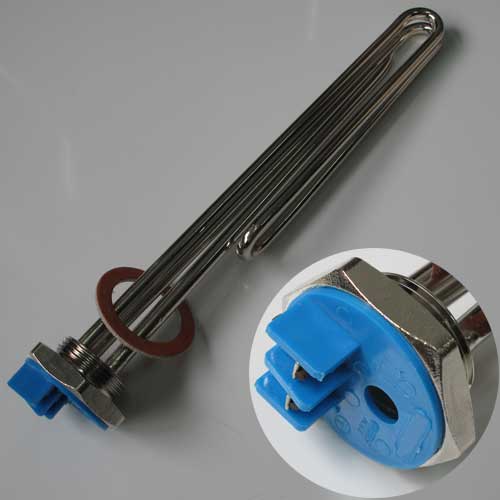Screw-in element: | 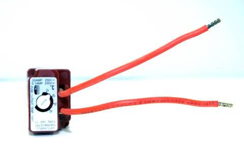VKF-11 thermostat: | Element & thermostat have separate electrical connections, so each can be connected (wired) separately to the Elon. Thus, **this element-thermostat combination is directly compatible with the Elon**. (No need to use the bridging wire or element adapter supplied with the Elon unit.) The thermostat pocket in the element is the right size for the VKF-11 thermostat. |
| Spiral element (flange type) with smaller diameter thermostat pocket: 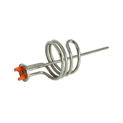 | TSE thermostat: Thermowatt (RTS) thermostat: 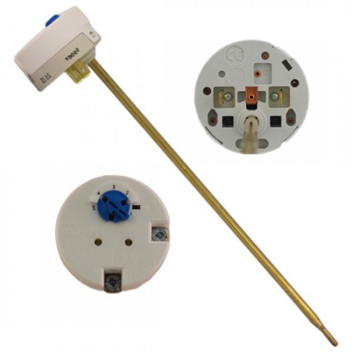 | The spiral element generally has a smaller thermostat pocket than the screw-in element. The TSE and Thermowatt (RTS) thermostats fit into this smaller pocket. The VKF-11 thermostat requires a larger pocket and does not fit into standard spiral element pockets. The TSE and Thermowatt thermostats normally clip directly into the element, but this won’t be the case when the Elon is connected. **Use the bridging wire and element adapter supplied with the Elon (see Figures 4.1 to 4.4 above) to connect the Elon to these thermostats and elements.** |
| **Location** | **Electricity generated kWh/kWp per year** |
| Bloemfontein | 2055 |
| Cape Town | 1762 |
| Durban | 1570 |
| Johannesburg / Pretoria | 1871 |
| Mbombela | 1766 |
| Port Elizabeth | 1698 |
| Upington | 2075 |
| **Number of solar PV modules** | **Showers per day\*** | **50%+ of daily hot water use provided for how many people?** | **How many people off-grid for hot water?** | **Solar PV array size** **(kWp)** | **Matching geyser element size** **(kW)** | **Geyser (water tank) size** **(litres)** |
| 3 modules |  |  |  | 1.0  | **3** | 100 - 150 |
| 4 modules |  |  |  | 1.2 – 1.3  | **3** | 100 - 150 |
| 5 modules |  |  |  | 1.5 – 1.7  | **2** | 100 – 150 |
| 8 modules |  |  |  | 2.4 – 2.7  | **4** | 150 – 200 |
| 10 modules |  |  |  | 3 – 3.5  | **4** | 200+ |
| **Solar + Elon** | **Annual average litres of water heated per day for X kWp installed solar capacity** | |||||||||||||||||
|---|---|---|---|---|---|---|---|---|---|---|---|---|---|---|---|---|---|---|
| **Location** | **kWh/kWp/yr** | **0.8 kWp** | **1 kWp** | **1.2 kWp** | **1.4 kWp** | **1.6 kWp** | **1.8 kWp** | **2 kWp** | **2.5 kWp** | **3 kWp** | **3.5 kWp** | |||||||
| Bloemfontein | 1894 | 80 | 99 | 119 | 139 | 159 | 179 | 199 | 249 | 298 | 348 | |||||||
| Cape Town | 1624 | 68 | 85 | 102 | 119 | 136 | 154 | 171 | 213 | 256 | 299 | |||||||
| Durban | 1447 | 61 | 76 | 91 | 106 | 122 | 137 | 152 | 190 | 228 | 266 | |||||||
| Jhb/Pretoria | 1724 | 72 | 91 | 109 | 127 | 145 | 163 | 181 | 226 | 272 | 317 | |||||||
| Mbombela | 1627 | 68 | 85 | 103 | 120 | 137 | 154 | 171 | 214 | 256 | 299 | |||||||
| Port Elizabeth | 1565 | 66 | 82 | 99 | 115 | 132 | 148 | 164 | 205 | 247 | 288 | |||||||
| Upington | 1912 | 80 | 100 | 121 | 141 | 161 | 181 | 201 | 251 | 301 | 352 | |||||||
| Saldanha | 1623 | 68 | 85 | 102 | 119 | 136 | 153 | 170 | 213 | 256 | 298 | |||||||
| **Solar + Elon** | **Number of showers per day (based on annual average) for X kWp installed solar capacity** | ||||||||||
| **Location** | **kWh/kWp/yr** | **0.8 kWp** | **1 kWp** | **1.2 kWp** | **1.4 kWp** | **1.6 kWp** | **1.8 kWp** | **2 kWp** | **2.5 kWp** | **3 kWp** | **3.5 kWp** |
| Bloemfontein | **1894** | **2.4** | **3.0** | **3.6** | **4.2** | **4.8** | **5.4** | **6.0** | **7.5** | **9.0** | **10.4** |
| Cape Town | **1624** | **2.0** | **2.6** | **3.1** | **3.6** | **4.1** | **4.6** | **5.1** | **6.4** | **7.7** | **9.0** |
| Durban | **1447** | **1.8** | **2.3** | **2.7** | **3.2** | **3.6** | **4.1** | **4.6** | **5.7** | **6.8** | **8.0** |
| Jhb/Pretoria | **1724** | **2.2** | **2.7** | **3.3** | **3.8** | **4.3** | **4.9** | **5.4** | **6.8** | **8.2** | **9.5** |
| Mbombela | **1627** | **2.1** | **2.6** | **3.1** | **3.6** | **4.1** | **4.6** | **5.1** | **6.4** | **7.7** | **9.0** |
| Port Elizabeth | **1565** | **2.0** | **2.5** | **3.0** | **3.5** | **3.9** | **4.4** | **4.9** | **6.2** | **7.4** | **8.6** |
| Upington | **1912** | **2.4** | **3.0** | **3.6** | **4.2** | **4.8** | **5.4** | **6.0** | **7.5** | **9.0** | **10.5** |
| Saldanha | **1623** | **2.0** | **2.6** | **3.1** | **3.6** | **4.1** | **4.6** | **5.1** | **6.4** | **7.7** | **9.0** |
| Solar + Elon | **Annual average % of hot water requirement supplied for 2 people each using 80 litres of hot water per day for X kWp installed solar capacity** | ||||||||||
| Location | kWh/kWp/yr | **0.8 kWp** | **1 kWp** | **1.2 kWp** | **1.4 kWp** | **1.6 kWp** | **1.8 kWp** | **2 kWp** | **2.5 kWp** | **3 kWp** | **3.5 kWp** |
| Bloemfontein | 1894 | **50%** | **62%** | **75%** | **87%** | **99%** | **112%** | **124%** | **155%** | **187%** | **218%** |
| Cape Town | 1624 | **43%** | **53%** | **64%** | **75%** | **85%** | **96%** | **107%** | **133%** | **160%** | **187%** |
| Durban | 1447 | **38%** | **47%** | **57%** | **66%** | **76%** | **85%** | **95%** | **119%** | **142%** | **166%** |
| Jhb/Pretoria | 1724 | **45%** | **57%** | **68%** | **79%** | **91%** | **102%** | **113%** | **142%** | **170%** | **198%** |
| Nelspruit | 1627 | **43%** | **53%** | **64%** | **75%** | **85%** | **96%** | **107%** | **134%** | **160%** | **187%** |
| Port Elizabeth | 1565 | **41%** | **51%** | **62%** | **72%** | **82%** | **92%** | **103%** | **128%** | **154%** | **180%** |
| Upington | 1912 | **50%** | **63%** | **75%** | **88%** | **100%** | **113%** | **126%** | **157%** | **188%** | **220%** |
| Saldanha | 1623 | **43%** | **53%** | **64%** | **75%** | **85%** | **96%** | **107%** | **133%** | **160%** | **186%** |
| **No. of cells per module** | **Module STC power rating (Wp)** | **Total peak power at STC in kWp for an array of X modules** | ||||||
|---|---|---|---|---|---|---|---|---|
| **3 modules** | **4 modules** | **5 modules** | **6 modules** | **2 x 4 (8) modules** | **2 x 5 (10) modules** | **2 x 6 (12) modules** | ||
| 60 | 250 | 0.75 | 1.00 | 1.25 | 1.50 | 2.00 | 2.50 | 3.00 |
| 60 | 255 | 0.77 | 1.02 | 1.28 | 1.53 | 2.04 | 2.55 | 3.06 |
| 60 | 260 | 0.78 | 1.04 | 1.30 | 1.56 | 2.08 | 2.60 | 3.12 |
| 60 | 265 | 0.80 | 1.06 | 1.33 | 1.59 | 2.12 | 2.65 | 3.18 |
| 60 | 270 | 0.81 | 1.08 | 1.35 | 1.62 | 2.16 | 2.70 | 3.24 |
| 60 | 275 | 0.825 | 1.10 | 1.375 | 1.65 | 2.20 | 2.75 | 3.30 |
| 60 | 280 | 0.84 | 1.12 | 1.40 | 1.68 | 2.24 | 2.80 | 3.36 |
| 60 | 285 | 0.855 | 1.14 | 1.425 | 1.71 | 2.28 | 2.85 | 3.42 |
| 60 | 290 | 0.87 | 1.16 | 1.45 | 1.74 | 2.32 | 2.90 | 3.48 |
| 72 | 295 | 0.885 | 1.18 | 1.475 | 1.77 | 2.36 | 2.95 | 3.54 **NOT ALLOWED** **(exceeds maximum rated Elon 100 voltage)** |
| 72 | 300 | 0.90 | 1.20 | 1.50 | 1.80 | 2.40 | 3.00 | 3.60 |
| 72 | 305 | 0.915 | 1.22 | 1.525 | 1.83 **NOT ALLOWED** **(exceeds maximum rated Elon 100 voltage)** | 2.44 | 3.05 | 3.66 |
| 72 | 310 | 0.93 | 1.24 | 1.55 | 1.86 | 2.48 | 3.10 | 3.72 |
| 72 | 315 | 0.945 | 1.26 | 1.575 | 1.89 | 2.52 | 3.15 | 3.78 |
| 72 | 320 | 0.96 | 1.28 | 1.60 | 1.92 | 2.56 | 3.20 | 3.84 |
| 72 | 325 | 0.975 | 1.30 | 1.625 | 1.95 | 2.60 | 3.25 | 3.90 |
| 72 | 330 | 0.99 | 1.32 | 1.65 | 1.98 | 2.64 | 3.30 | 3.96 |
| 72 | 335 | 1.005 | 1.34 | 1.675 | 2.01 | 2.68 | 3.35 | 4.02 |
| 72 | 340 | 1.02 | 1.36 | 1.70 | 2.04 | 2.72 | 3.40 | 4.08 |
| **No. of cells** | **Module STC power rating (Wp)** | **Module NOCT Vmpp (V)** | **Module NOCT Impp (A)** | **Best element size match (rated power in kW @ 230 V AC) for an array of X modules** | ||||||
|---|---|---|---|---|---|---|---|---|---|---|
| **3 modules** | **4 modules** | **5 modules** | **6 modules** | **2 x 4 (8) modules** | **2 x 5 (10) modules** | **2 x 6 (12) modules** | ||||
| 60 | 250 – 290 | 28 – 29 | 6.5 – 7.3 | 4 kW | 3 kW | 2 kW | 2 kW | 4 kW | 4 kW | 4 kW |
| 72 | 295 - 340 | 33 – 35 | 6.5 – 7.3 | 3 kW | 2 kW | 2 kW | NA | 4 kW | 4 kW | NA |
| **No. of cells** | **Module STC power rating (Wp)** | **Module NOCT Vmpp (V)** | **Module NOCT Impp (A)** | **Best element size match (rated power in kW @ 230 V AC) for an array of X modules** | ||||||
|---|---|---|---|---|---|---|---|---|---|---|
| **3 modules** | **4 modules** | **5 modules** | **6 modules** | **2 x 4 (8) modules** | **2 x 5 (10) modules** | **2 x 6 (12) modules** | ||||
| 60 | 250 – 290 | 28 – 29 | 6.5 – 7.3 | 3 kW | 2\* or 4 kW | 3 kW | NR | NR | NR | 3 kW |
| 72 | 295 - 340 | 33 – 35 | 6.5 – 7.3 | 4 kW | 3 kW | 3\* kW | NA | NR | 3 kW | NA |
| **Rated input voltage** | 250V AC, 220V DC |
| **Rated input current** | 25A AC, 20A DC |
| **Mains (AC) voltage range** | -50% to +100% (but will disconnect all loads when breach is greater than +/- 15%) |
| **System power supply** | Solar or 230V AC mains |
| **Shutdown** | Sufficient power supply capacity to manage processor, switching and data storage if both mains and solar supply fail |
| **Solar voltage** | 20 – 220 V DC |
| **Solar energy availability** | Automatically determines availability of sufficient solar energy before supplying load from solar modules |
| **Efficiency control** | Can be adjusted to run from “solar only” to substantial AC mains power usage |
| **Override switch** | A request (override) switch to force the managed load to use AC mains for one heating cycle is provided |
| **Thermostat** | Uses the standard normally open thermostat switch associated with the geyser element as a sensor only, with less than 10mA sense current, to control power to the element |
| **Reverse polarity protection** | Protected against reverse connection of solar array |
| **Switching timing** | Built-in random numbers generation staggers switching times where more than one Elon 100 is deployed |
| **Enclosure ingress protection rating** | IP65 |
| **Annual energy production compared to inverter-based system** | > 90% when solar array and geyser element are matched correctly |
| **Number of solar PV modules** | **Showers per day\*** | **50%+ of daily hot water use provided for how many people?** | **How many people off-grid for hot water?** | **Solar PV array size** **(kWp)** | **Matching geyser element size** **(kW)** | **Geyser (water tank) size** **(litres)** |
| 3 modules |  |  |  | 1.0  | **3** | 100 - 150 |
| 4 modules |  |  |  | 1.2 – 1.3  | **3** | 100 - 150 |
| 5 modules |  |  |  | 1.5 – 1.7  | **2** | 100 – 150 |
| 8 modules |  |  |  | 2.4 – 2.7  | **4** | 150 – 200 |
| 10 modules |  |  |  | 3 – 3.5  | **4** | 200+ |
| **Lights** | **Meaning** | |
| ⏺⏺ | Mains (**red**) light flashing | Grid (mains) electricity is being used to heat water |
| ⏺⏺ | Solar (**green**) light flashing | Solar power is being used to heat water. Rate of flashing indicates rate of solar energy supply |
| ⏺⏺ | **Red** & **green** alternating | No power is being supplied to the geyser element. (Either the water is on temperature already, or the unit is in solar mode and there is not sufficient sunlight) |
| ⏺⏺ ⏺⏺ | **Red** or **green** flashing very fast | Isolation fault (contact electrician) |
| ⏺⏺ | **Red** light **ON** | Solar power switched off (only grid power allowed to geyser). Press and hold override button for **15 seconds** to switch solar power on or off. **To switch off both solar and grid power**, turn the dial to SOLAR ONLY and then switch off the solar power with the override button as described. |
| ⏺⏺ | Both lights **OFF** | No power to unit (e.g. no sun and a power failure, or no sun and geyser breaker at DB board is switched off) |
| **Desired state** | **Actions** | **DB board geyser switch** | **Controller dial position** | **Lights** |
| **✓ Solar ON** **✓ Grid ON** | This is the default state. | ON | Anywhere outside the “Solar Only” zone | Normal operation (green and/or red flashing or both alternating) |
| **✓ Solar ON** **🗶 Grid OFF** | Turn controller dial anti-clockwise to the “Solar Only” zone indicated on the controller. **Note:** can still boost with grid power for one heating cycle by pressing the Override button for **5s**. | ON | In the “Solar Only” zone | Green flashing or both lights alternating. Red would flash if override button has been used. |
| **🗶 Solar OFF** **✓ Grid ON** | Press Override button for 15s until the red light switches on permanently. Grid power is now always ON (24 hours per day). | ON | Anywhere outside the “Solar Only” zone | Red light on |
| **🗶 Solar OFF** **🗶 Grid OFF** | Turn efficiency dial all the way anti-clockwise into the "Solar Only" zone. Press Override button for **15s** until the red light switches on permanently. | ON | In the “Solar Only” zone | Red light on |
| **Issue** | **Possible causes** | **What to do** |
|---|---|---|
| Water temperature too low | 1. High hot water usage levels 2. Cloudy or rainy day 3. Dirty solar modules 4. Mains circuit breaker has tripped 5. Thermostat connection or thermostat defective | 1. Press override button (3.3) OR Reduce efficiency setting (3.2) OR Reduce hot water use (3.5) OR Add additional solar modules to your solar installation (**first consult** with your installer) 1. See a. above 2. Inspect solar modules. If they are soiled, clean them with water and sponge (4.1) 3. Check mains circuit breaker 4. Call electrician for inspection |
| Water temperature remains low after mains power boost | 1. Sufficient time has not been provided for water to be heated after override button has been pressed 2. It is a cloudy day and there is a mains power failure 3. There is an electrical fault or the Elon 100 is defective 4. Thermostat connection or thermostat defective | 1. Wait for 2 hours after pressing the override button 2. You will have to wait until either the solar or grid power returns to heat the water 3. Check if only the mains light on the Elon 100 controller starts flashing after you press the override button for 10 seconds. If it does not and your water remains cold, call your electrician to inspect the installation for any electrical fault. 4. Call electrician for inspection |
| Water temperature too high | 1. Thermostat temperature setting is high and you are using hot water from a tap close to the geyser 2. Thermostat connection or thermostat defective | 1. Reduce thermostat temperature set point OR Open the cold water tap first OR Install a thermostatic mixing valve 1. Call electrician for inspection. |
| Hot water production is lower than it used to be | 1. Dirty solar modules 2. Trees / plants have grown and are causing shaded areas on solar modules 3. Damage to solar modules | 1. Inspect solar modules. If they are soiled, clean them with water and sponge (4.1) 2. Trim trees and plants 3. Installer or electrician should test solar array power production in sunny conditions and compare with specifications. If one or more modules are damaged and they are still under warranty, contact manufacturer for replacement |
| Both indicator lights off | 1. Power failure and overcast / night-time 2. Geyser breaker at DB board switched off | 1. Wait until power or sun returns and check if any indicator light comes on. 2. Switch on breaker at DB board. |
| Red or green indicator light flashing very fast | 1. Isolation fault | 1. Please call your electrician. |
| **Customer name** | **Date** | **Elon®** **serial no.** | |||||
| **Installation address** | |||||||
| **Installer name** | **Installer signature** | ||||||
| **No.** | **Action** | **Result** | **Units** |
| **2** | Confirm **correct wiring** and confirm **DC polarity** to Elon® as per basic wiring diagram on next page. Also confirm test meter wires are connected correctly, black to common! | **🞏** | |
| **3** | **Confirm correct voltages and currents of all connections through the following steps:** | ||
| 3a | Confirm open / closed **thermostat** voltages (11 – 14 V DC open, 0 V DC closed). Leave thermostat in closed position for rest of testing. If water is already at setpoint (e.g. 55 or 60 °C), indicated by a solid green light on the controller, increase thermostat temperature setting or open a hot water tap in the house to drain some hot water. | V DC (open) | |
| V DC (closed) | |||
| 3b | Confirm controller wire is connected properly. The connections should “click” into place and appropriate LEDs should indicate (be active). | **🞏** | |
| 3c | With dial on “SOLAR ONLY” and **solar power flowing to element** (green LED flashing), confirm same **DC voltage to element** as measured at solar terminals. | V DC solar | |
| V DC element | |||
| 3d | With **DC clamp meter** confirm that there is an **active current through element** by measuring the current of one of the wires going from Elon® to element. | A DC | |
| 3e | Turn dial to “MAINS ONLY”. Note that the Elon® will only switch to mains **5 min** after mains power switch-on or reconnection. With **mains power flowing to element** (red LED flashing), confirm same **AC voltage to element** as measured at mains terminals (should be approx. 230V AC). | V AC mains | |
| V AC element | |||
| 3f | With **AC clamp meter** confirm **active current through element** of between 9 and 18 Amps depending on element rating. | A AC | |
| **4** | If you used a test controller for commissioning, remember to plug the wire from the installed controller back into the Elon® and check functioning. | **🞏** | |
| **5** | Set thermostat back to original setting. | **🞏** | |
| **6** | Set control dial to setting “**2**” (the 6 o’clock position). | **🞏** | |
| **Customer name** | **Date** | **Elon®** **serial no.** | |||||
| **Installation address** | |||||||
| **Installer name** | **Installer signature** | ||||||
| **No.** | **Action** | **Result** | **Units** |
|---|---|---|---|
| **DC Side Inspection (NOT a full solar PV installation checklist – we recommend PV GreenCard)** | |||
| **1** | Check that all panels are mounted securely | **🞏** | |
| **2** | Check that mounting structure is grounded | **🞏** | |
| **3** | Check that all panels are the same power rating and model | **🞏** | |
| **4** | Check all insulation on PV cables | **🞏** | |
| **5** | Check that PV cable size is as specified for installation | **🞏** | |
| **6** | Check that all connectors are securely fastened | **🞏** | |
| **7** | Check that all PV cables are properly routed and secured | **🞏** | |
| **8** | Check that DC circuit breaker OR DC isolator + fuse are installed within 2m of geyser & in line of sight | **🞏** | |
| **9** | Check that no PV cables are coiled | **🞏** | |
| **10** | Check that PV cables are connected to the solar input terminals on the Elon 100 and with correct polarity (see wiring diagram on last page) | **🞏** | |
| **AC Side Inspection** | |||
| **11** | Check that AC isolator is installed within 2m of geyser & in line of sight | **🞏** | |
| **12** | Check that AC wires are connected to the correct terminals on the Elon 100 (see wiring diagram on last page) | **🞏** | |
| **Elon 100 inspection** | |||
| **13** | Check that Elon is installed within 2m of geyser (maximum wire length between Elon and geyser is 3m). If installed outside, the Elon should be protected from the elements and installed with glands facing downward. | **🞏** | |
| **14** | Check that two wires run between the Elon’s “element” terminals and the “element” terminals on the green element adapter and that they are securely connected at both ends. | **🞏** | |
| **15** | Check that two wires run between the Elon’s “thermostat” terminals and the thermostat, and that they are securely connected at both ends. | **🞏** | |
| **16** | Check that all wiring is at least 2.5mm² | **🞏** | |
| **17** | **IMPORTANT:** Check that element adapter’s male spade terminals are securely and correctly seated in the element’s female terminals. Do a tug test on each side to test that it is secure. | **🞏** | |
| **18** | Check that ALL labels have been applied as per the label diagram in the Elon installation manual (installation diagram, “Warning! photovoltaic power source” and 2 x “Warning, Dual Supply”). | **🞏** | |
| **19** | Check that controller (remote control) has been securely installed in an accessible place and that both ends of the communication cable are properly inserted. | **🞏** | |
| **No.** | **Action** | **Result** | **Units** |
|---|---|---|---|
| **20** | Confirm **correct wiring** and confirm **DC polarity** to Elon® as per basic wiring diagram after this table. Also confirm test meter wires are connected correctly, black to common! | **🞏** | |
| **21** | **Confirm correct voltages and currents of all connections through the following steps:** | ||
| 21a | Confirm open / closed **thermostat** voltages (11 – 14 V DC open, 0 V DC closed). Leave thermostat in closed position for rest of testing. If water is already at setpoint (e.g. 55 or 60 °C), indicated by a solid green light on the controller, increase thermostat temperature setting or open a hot water tap in the house to drain some hot water. | V DC (open) | |
| V DC (closed) | |||
| 21b | Confirm controller wire is connected properly. The connections should “click” into place and appropriate LEDs should indicate (be active). | **🞏** | |
| 21c | With dial on “SOLAR ONLY” and **solar power flowing to element** (green LED flashing), confirm same **DC voltage to element** as measured at solar terminals. | V DC solar | |
| V DC element | |||
| 21d | With **DC clamp meter** confirm that there is an **active current through element** by measuring the current of one of the wires going from Elon® to element. | A DC | |
| 21e | Turn dial to “MAINS ONLY”. Note that the Elon® will only switch to mains **5 min** after mains power switch-on or reconnection. With **mains power flowing to element** (red LED flashing), confirm same **AC voltage to element** as measured at mains terminals (should be approx. 230V AC). | V AC mains | |
| V AC element | |||
| 21f | With **AC clamp meter** confirm **active current through element** of between 9 and 18 Amps depending on element rating. | A AC | |
| **22** | If you used a test controller for commissioning, remember to plug the wire from the installed controller back into the Elon® and check functioning. | **🞏** | |
| **23** | Set thermostat back to original setting. | **🞏** | |
| **24** | Set control dial to setting “**2**” (the 6 o’clock position). | **🞏** | |
| **Elon® 100 User Manual** | [**www.poweroptimal.com/manuals**](http://www.poweroptimal.com/manuals) |
| **Training videos for electricians** | [**www.poweroptimal.com/elon-100-training**](https://www.poweroptimal.com/elon-100-training/) |
| **Online User Instructions Video** | [**www.poweroptimal.com/elon100**](http://www.poweroptimal.com/elon100) |
| **Online Elon® Basic Training Course** | [**https://moolmaninstitute.com/p/elon-course**](https://moolmaninstitute.com/p/elon-course) |
| **Lights** | **Meaning** | |
| ⏺⏺ | **Green** light **ON** | **Geyser on temperature** |
| ⏺⏺ | **Green** light **flashing** | Heating with solar |
| ⏺⏺ | **Red** light **ON** | Mains power available (mains power to Elon® unit on) |
| ⏺⏺ | **Red** light **flashing** | Heating with mains |
| ⏺⏺ | **Both** lights **ON** | Geyser is on temperature. Mains power available (mains power to Elon® unit on) |
| ⏺⏺ | **Red** light **ON** & **Green** light **flashing** | Heating with solar. Mains power available (mains power to Elon® unit on) |
| ⏺⏺ | **Red** & **Green** light **flashing fast** | Isolation fault (contact electrician) |
| ⏺⏺ | Both lights **OFF** | No power to unit (for example: no sun plus a power failure, or no sun plus geyser breaker at DB board is switched off) OR supply voltage outside specifications |
| **Element type** | **Compatible thermostat type** | **Comments** |
|---|---|---|
| Screw-in element: | VKF-11 thermostat: | Element & thermostat have separate electrical connections, so each can be connected (wired) separately to the Elon®. Thus, **this element-thermostat combination is directly compatible with the Elon®**. (No need to use the bridging wire or element adapter supplied with the Elon® unit.) The thermostat pocket in the element is the right size for the VKF-11 thermostat. **Do not connect the thermostat in line with the element. Connect the two thermostat wires to the two terminals marked “thermostat” on the Elon 100 unit. Connect the element separately to the two terminals marked “element” on the Elon 100 unit.** |
| Spiral element (flange type) with smaller diameter thermostat pocket:  | TSE thermostat: Thermowatt (RTS) thermostat:  | The spiral element generally has a smaller thermostat pocket than the screw-in element. The TSE and Thermowatt (RTS) thermostats fit into this smaller pocket. The VKF-11 thermostat requires a larger pocket and does not fit into standard spiral element pockets. The TSE and Thermowatt thermostats normally clip directly into the element, but this won’t be the case when the Elon® is connected. **Use the wiring kit or element adapter supplied with the Elon® (see Figures 4.1 and 4.2 above) to connect the Elon® to these thermostats and elements.** |
| **Location** | **Electricity generated kWh/kWp per year** |
| Bloemfontein | 2055 |
| Cape Town | 1762 |
| Durban | 1570 |
| Johannesburg / Pretoria | 1871 |
| Mbombela | 1766 |
| Port Elizabeth | 1698 |
| Upington | 2075 |
| **Solar PV array size** **(kWp)** | **Showers per day\*** | **50%+ of daily hot water use provided for how many people?** | **How many people off-grid for hot water?** | **Typical number of solar PV modules** |
| **1 – 1.6** |  |  |  | **2 - 3 modules** |
| **1.6 – 2** |  |  |  | **3 - 4 modules** |
| **2 – 3** |  |  |  | **4 - 5 modules** |
| **3 – 4** **(two parallel PV strings)** |  |  |  | **6 - 8 modules** |
| **Solar + Elon®** | **Annual average litres of water heated per day for X kWp installed solar capacity** | |||||||||||||||||
|---|---|---|---|---|---|---|---|---|---|---|---|---|---|---|---|---|---|---|
| **Location** | **kWh/kWp/yr** | **0.8 kWp** | **1 kWp** | **1.2 kWp** | **1.4 kWp** | **1.6 kWp** | **1.8 kWp** | **2 kWp** | **2.5 kWp** | **3 kWp** | **3.5 kWp** | |||||||
| Bloemfontein | 1894 | 80 | 99 | 119 | 139 | 159 | 179 | 199 | 249 | 298 | 348 | |||||||
| Cape Town | 1624 | 68 | 85 | 102 | 119 | 136 | 154 | 171 | 213 | 256 | 299 | |||||||
| Durban | 1447 | 61 | 76 | 91 | 106 | 122 | 137 | 152 | 190 | 228 | 266 | |||||||
| Jhb/Pretoria | 1724 | 72 | 91 | 109 | 127 | 145 | 163 | 181 | 226 | 272 | 317 | |||||||
| Mbombela | 1627 | 68 | 85 | 103 | 120 | 137 | 154 | 171 | 214 | 256 | 299 | |||||||
| Port Elizabeth | 1565 | 66 | 82 | 99 | 115 | 132 | 148 | 164 | 205 | 247 | 288 | |||||||
| Upington | 1912 | 80 | 100 | 121 | 141 | 161 | 181 | 201 | 251 | 301 | 352 | |||||||
| Saldanha | 1623 | 68 | 85 | 102 | 119 | 136 | 153 | 170 | 213 | 256 | 298 | |||||||
| **Solar + Elon®** | **Number of showers per day (based on annual average) for X kWp installed solar capacity** | ||||||||||
| **Location** | **kWh/kWp/yr** | **0.8 kWp** | **1 kWp** | **1.2 kWp** | **1.4 kWp** | **1.6 kWp** | **1.8 kWp** | **2 kWp** | **2.5 kWp** | **3 kWp** | **3.5 kWp** |
| Bloemfontein | **1894** | **2.4** | **3.0** | **3.6** | **4.2** | **4.8** | **5.4** | **6.0** | **7.5** | **9.0** | **10.4** |
| Cape Town | **1624** | **2.0** | **2.6** | **3.1** | **3.6** | **4.1** | **4.6** | **5.1** | **6.4** | **7.7** | **9.0** |
| Durban | **1447** | **1.8** | **2.3** | **2.7** | **3.2** | **3.6** | **4.1** | **4.6** | **5.7** | **6.8** | **8.0** |
| Jhb/Pretoria | **1724** | **2.2** | **2.7** | **3.3** | **3.8** | **4.3** | **4.9** | **5.4** | **6.8** | **8.2** | **9.5** |
| Mbombela | **1627** | **2.1** | **2.6** | **3.1** | **3.6** | **4.1** | **4.6** | **5.1** | **6.4** | **7.7** | **9.0** |
| Port Elizabeth | **1565** | **2.0** | **2.5** | **3.0** | **3.5** | **3.9** | **4.4** | **4.9** | **6.2** | **7.4** | **8.6** |
| Upington | **1912** | **2.4** | **3.0** | **3.6** | **4.2** | **4.8** | **5.4** | **6.0** | **7.5** | **9.0** | **10.5** |
| Saldanha | **1623** | **2.0** | **2.6** | **3.1** | **3.6** | **4.1** | **4.6** | **5.1** | **6.4** | **7.7** | **9.0** |
| Solar + Elon® | **Annual average % of hot water requirement supplied for 2 people each using 80 litres of hot water per day for X kWp installed solar capacity** | ||||||||||
| Location | kWh/kWp/yr | **0.8 kWp** | **1 kWp** | **1.2 kWp** | **1.4 kWp** | **1.6 kWp** | **1.8 kWp** | **2 kWp** | **2.5 kWp** | **3 kWp** | **3.5 kWp** |
| Bloemfontein | 1894 | **50%** | **62%** | **75%** | **87%** | **99%** | **112%** | **124%** | **155%** | **187%** | **218%** |
| Cape Town | 1624 | **43%** | **53%** | **64%** | **75%** | **85%** | **96%** | **107%** | **133%** | **160%** | **187%** |
| Durban | 1447 | **38%** | **47%** | **57%** | **66%** | **76%** | **85%** | **95%** | **119%** | **142%** | **166%** |
| Jhb/Pretoria | 1724 | **45%** | **57%** | **68%** | **79%** | **91%** | **102%** | **113%** | **142%** | **170%** | **198%** |
| Nelspruit | 1627 | **43%** | **53%** | **64%** | **75%** | **85%** | **96%** | **107%** | **134%** | **160%** | **187%** |
| Port Elizabeth | 1565 | **41%** | **51%** | **62%** | **72%** | **82%** | **92%** | **103%** | **128%** | **154%** | **180%** |
| Upington | 1912 | **50%** | **63%** | **75%** | **88%** | **100%** | **113%** | **126%** | **157%** | **188%** | **220%** |
| Saldanha | 1623 | **43%** | **53%** | **64%** | **75%** | **85%** | **96%** | **107%** | **133%** | **160%** | **186%** |
| **Solar PV array size** **(kWp)** | **Best matching geyser element size** **(kW)** | **2nd choice geyser element size\*** **(kW)** | **Geyser (water tank) size** **(litres)** |
| **1 – 1.6** | **4** | 3 | 100 - 200 |
| **1.6 – 2** | **3** | 4 or 2 | 100 - 200 |
| **2 - 3** | **3** | 4 | 150 – 300 |
| **2 – 4** **(two parallel PV strings)** | **4** | NA | 200+ |
| **Rated input voltage** | 250V AC, 250V DC |
| **Rated input current** | 25A AC, 20A DC |
| **Mains (AC) voltage range** | -50% to +100% (but will disconnect all loads when breach is greater than +/- 15%) |
| **System power supply** | Solar or 230V AC mains |
| **Power consumption** | <3W on mains power; <0.5W on solar power |
| **Shutdown** | Sufficient power supply capacity to manage processor, switching and data storage if both mains and solar supply fail |
| **Solar voltage (Voc at STC)** | 20 – 250 V DC |
| **Solar energy availability** | Automatically determines availability of sufficient solar energy before supplying load from solar modules |
| **Controller settings** | Can be adjusted to run from “solar only” (100% solar energy use) to "mains only" (no solar energy use) |
| **Thermostat** | Uses the standard normally open thermostat switch associated with the geyser element as a sensor only, with less than 10mA sense current, to control power to the element |
| **Reverse polarity protection** | Protected against reverse connection of solar array |
| **Enclosure ingress protection rating** | Elon 100 main unit: IP65 Elon 100 remote control: IP40 (install indoors or in waterproof enclosure) |
| **Maximum distance Elon® unit to controller** | 10 m |
| **Annual energy production compared to inverter-based system** | > 90% when solar array and geyser element are matched correctly |
| **Standards conformance** | IEC / SANS 60669-1, 60669-2-1, 60730-1, 60335-1, 60335-2-21, CISPR 11 & IEC 61000-6-1 |
| **Dimensions & weight** | Elon® 100 main unit: 200 x 150 x 60 mm (LxWxH), 1.75 kg. Controller: 50 x 72 x 41 mm (LxWxH) |
| **Patents** | ZA 2019/02129 |
| Type of installation | Individual residential premises | Terrestrial production plant | Service / Industrial / Agricultural Buildings |
| Lcrit (in meter) | 115/Ng | 200/Ng | 450/Ng |
| **City** | **Lightning strike density Ng (strikes/km²/yr)** | **Lcrit (m)** | |
|---|---|---|---|
| **Individual residential premises** | **Service / industrial / agricultural buildings** | ||
| Cape Town | 0.02 to 4 | 29 | 113 |
| Stellenbosch | 0.02 to 4 | 29 | 113 |
| Worcester | 0.02 to 4 | 29 | 113 |
| George | 0.02 to 4 | 29 | 113 |
| Saldanha | 0.02 to 4 | 29 | 113 |
| Port Elizabeth | 0.02 to 4 | 29 | 113 |
| East London | 4 to 6 | 19 | 75 |
| King Williams Town | 4 to 6 | 19 | 75 |
| Beaufort-West | 4 to 6 | 19 | 75 |
| Musina | 4 to 6 | 19 | 75 |
| Britstown | 6 to 15 | 8 | 30 |
| Durban | 6 to 15 | 8 | 30 |
| Upington | 6 to 15 | 8 | 30 |
| Pietermaritzburg | 15 to 21 | 5 | 21 |
| Greytown | 15 to 21 | 5 | 21 |
| Polokwane | 15 to 21 | 5 | 21 |
| Bloemfontein | 15 to 21 | 5 | 21 |
| Queenstown | 15 to 21 | 5 | 21 |
| Vryburg | 15 to 21 | 5 | 21 |
| Mahikeng | 15 to 21 | 5 | 21 |
| Mbombela (Nelspruit) | 15 to 21 | 5 | 21 |
| Kimberley | 21 to 27 | 4 | 16 |
| Pretoria | 21 to 27 | 4 | 16 |
| Vereeniging | 21 to 27 | 4 | 16 |
| Welkom | 21 to 27 | 4 | 16 |
| Johannesburg | 27 to 33 | 3.5 | 13 |
| Ermelo | 33 to 42 | 2.5 | 10 |
| Newcastle | 33 to 42 | 2.5 | 10 |
| **Lights** | **Meaning** | |
| ⏺⏺ | **Green** light **ON** | **Geyser on temperature** |
| ⏺⏺ | **Green** light **flashing** | Heating with solar |
| ⏺⏺ | **Red** light **ON** | Mains power available (power to Elon® unit on) |
| ⏺⏺ | **Red** light **flashing** | Heating with mains |
| ⏺⏺ | **Both** lights **ON** | Geyser is on temperature. Mains power available (mains power to Elon® unit on) |
| ⏺⏺ | **Red** light **ON** & **Green** light **flashing** | Heating with solar. Mains power available (mains power to Elon® unit on) |
| ⏺⏺ | **Red** & **Green** light **flashing fast** | Isolation fault (contact electrician) |
| ⏺⏺ | Both lights **OFF** | No power to unit (for example: no sun plus a power failure, or no sun plus geyser breaker at DB board is switched off) OR supply voltage outside specifications |
| **Elon® 100 Installation Guide & Quick Reference User Guide** | [**www.poweroptimal.com/manuals**](http://www.poweroptimal.com/manuals) |
| **Online User Instructions Video** | [**www.poweroptimal.com/elon100**](http://www.poweroptimal.com/elon100) |
| **Online Elon® Basic Training Course** | [**https://moolmaninstitute.com/p/elon-course**](https://moolmaninstitute.com/p/elon-course) |
| **Solar PV array size** **(kWp)** | **Showers per day\*** | **50%+ of daily hot water use provided for how many people?** | **How many people off-grid for hot water?** | **Typical number of solar PV modules** |
| **1 – 1.6** |  |  |  | **2 - 3 modules** |
| **1.6 – 2** |  |  |  | **3 - 4 modules** |
| **2 – 3** |  |  |  | **4 - 5 modules** |
| **3 – 4** **(two parallel PV strings)** |  |  |  | **6 - 8 modules** |
| **Solar PV array size** **(kWp)** | **Best matching geyser element size** **(kW)** | **2nd choice geyser element size\*** **(kW)** | **Geyser (water tank) size** **(litres)** |
| **1 – 1.6** | **4** | 3 | 100 - 200 |
| **1.6 – 2** | **3** | 4 or 2 | 100 - 200 |
| **2 – 3** | **3** | 4 | 150 – 300 |
| **2 – 4** **(two parallel PV strings)** | **4** | NA | 200+ |
| **Lights** | **Meaning** | |
| ⏺⏺ | **Green** light **ON** | **Geyser on temperature** |
| ⏺⏺ | **Green** light **flashing** | Heating with solar |
| ⏺⏺ | **Red** light **ON** | Mains power available (power to Elon® unit on) |
| ⏺⏺ | **Red** light **flashing** | Heating with mains |
| ⏺⏺ | **Both** lights **ON** | Geyser is on temperature. Mains power available (mains power to Elon® unit on) |
| ⏺⏺ | **Red** light **ON** & **Green** light **flashing** | Heating with solar. Mains power available (mains power to Elon® unit on) |
| ⏺⏺ | **Red** & **Green** light **flashing fast** | Isolation fault (contact electrician) |
| ⏺⏺ | Both lights **OFF** | No power to unit (for example: no sun plus a power failure, or no sun plus geyser breaker at DB board is switched off) OR supply voltage outside specifications |
| **Setting** | **How to set it** | **Benefits & comments** |
| **Mains power off** | Turn dial to **SOLAR ONLY** | You will have hot water on your return, and it will cost you nothing. It will also prevent Legionella growth in your geyser. |
| **Both Mains & Solar power off** | Turn dial to **MAINS ONLY** and **switch off geyser at distribution board** | Remember to switch system on when you return. |
| **Issue** | **Possible causes** | **What to do** |
|---|---|---|
| Water temperature too low | 1. High hot water usage levels 2. Cloudy or rainy day 3. Dirty solar modules 4. Mains circuit breaker has tripped 5. Thermostat connection or thermostat defective | 1. Turn control dial clockwise (2.3) OR Reduce hot water use (2.5) OR Add additional solar modules to your solar installation (**first consult** with your installer) 1. See a. above 2. Inspect solar modules. If they are soiled, clean them with water and sponge (4.1) 3. Check mains circuit breaker 4. Call electrician for inspection |
| Water temperature remains low after turning dial to "MAINS ONLY". (Note: the red LED light should start flashing once dial is turned to “MAINS ONLY”, indicating that the water is being heated.) | 1. Sufficient time has not been provided for water to be heated after dial has been turned 2. It is a cloudy day and there is a mains power failure 3. There is an electrical fault or the Elon® 100 is defective 4. Thermostat connection or thermostat or element defective | 1. Wait for 2 hours after turning the dial to “MAINS ONLY”. 2. You will have to wait until either the solar or grid power returns to heat the water 3. Check if the mains light on the Elon® 100 controller starts flashing after you turn the dial to "MAINS ONLY". If it does not and your water remains cold, call your electrician to inspect the installation for any electrical fault. 4. Call electrician for inspection |
| Water temperature too high | 1. Thermostat temperature setting is high and you are using hot water from a tap close to the geyser 2. Thermostat connection or thermostat defective | 1. Reduce thermostat temperature set point OR Open the cold water tap first OR Install a thermostatic mixing valve 1. Call electrician for inspection. |
| Hot water production is lower than it used to be | 1. Dirty solar modules 2. Trees / plants have grown and are causing shaded areas on solar modules 3. Damage to solar modules | 1. Inspect solar modules. If they are soiled, clean them with water and sponge (4.1) 2. Trim trees and plants 3. Installer or electrician should test solar array power production in sunny conditions and compare with specifications. If one or more modules are damaged and they are still under warranty, contact manufacturer for replacement |
| Both indicator lights off | 1. There is a power failure and it is overcast or night-time 2. Geyser breaker at DB board switched off and it is overcast or night-time 3. Mains power is over- or under-voltage | 1. Wait until power or sun returns and check if any indicator light comes on. 2. Switch on breaker at DB board. 3. If actions in a. and b. above do not resolve the issue, call your electrician. |
| Red or green indicator light flashing very fast | 1. Isolation fault | 1. Please call your electrician. |